



FANUC vs Siemens: CNC Controls for Slant Bed CNC Lathe Machines
Quick Answer: Both FANUC 0i-TF Plus and Siemens SINUMERIK 828D are suitable for slant bed CNC lathe machines when properly configured. FANUC is worth prioritizing for manufacturers with an established FANUC programming and maintenance environment, while Siemens is worth considering for ShopTurn programming and complex turning applications. The final decision should depend on software options, machining channels, machine accuracy, productivity, and total cost of ownership—not the CNC brand alone.
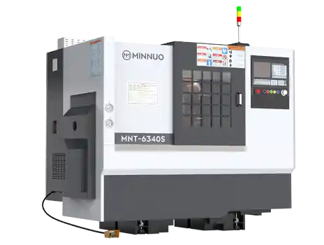
The CNC control system in a slant bed CNC lathe machine performs much more than executing machining programs. It manages toolpath interpolation, servo-axis coordination, tool compensation, spindle control, and auxiliary machine functions.
For CNC lathe purchasing engineers, choosing between FANUC and Siemens involves three practical questions:
- Which control system can meet the machining requirements of the intended workpieces?
- Which system integrates more effectively with existing programming, operations, and factory automation?
- Which complete machine configuration offers better long-term value when machining performance and operating costs are considered?
This guide compares FANUC 0i-TF Plus and Siemens SINUMERIK 828D, rather than treating every CNC controller from either manufacturer as technically equivalent.
1. FANUC 0i-TF Plus vs Siemens 828D: Technical Specifications Compared
FANUC 0i-TF Plus is primarily designed for CNC turning applications, while Siemens SINUMERIK 828D is available in performance configurations supporting turning, milling, and related machining operations. Both platforms can support advanced machining functions, but their actual capabilities depend on the software version, axis configuration, machining channels, and enabled options.
1.1 How Do the Axis Control, Machining Channels, and System Configurations Compare?
The following comparison is based on FANUC's published 0i-TF Plus specifications and Siemens' 2025 SINUMERIK 828D technical data.
| Technical Feature | FANUC 0i-TF Plus | Siemens SINUMERIK 828D |
|---|---|---|
| Primary application | CNC turning | CNC turning, milling, and related applications |
| Control platform | Turning configuration within the 0i-F Plus family | SW24x, SW26x, SW28x performance versions |
| Maximum controlled axes | 12 axes listed in the technical specifications | 8, 11, or 18 axes depending on version |
| Maximum machining paths/channels | 2 control paths | 1 or 2 machining channels depending on version |
| Standard X/Z turning | Supported | Supported |
| C-axis and live tooling | Configuration-dependent | Configuration-dependent |
| Twin-turret control | Available with a suitable dual-path configuration | Requires appropriate machining channels and OEM integration |
| G-code programming | Supported | Supported |
| Conversational programming | MANUAL GUIDE i and related solutions | ShopTurn and related solutions |
| Machine data connectivity | FOCAS and related interfaces | OPC UA and related solutions |
| Finished-part accuracy | Depends on complete machine design and setup | Depends on complete machine design and setup |
Important clarification regarding FANUC axis specifications
The technical specification table on FANUC's official 0i-TF Plus product page lists:
- Maximum controlled axes: 12 total.
- Maximum controlled axes per path: 9.
- Maximum simultaneously controlled axes per path: 4.
- Maximum control paths: 2.
However, other descriptive text on the same product page refers to different axis counts, including 15 axes for a single-path configuration and 18 axes for a dual-path configuration.
These figures should therefore not be treated as universal specifications for every delivered 0i-TF Plus configuration.
Before placing an order, buyers should obtain the exact controller model, software configuration, enabled options, and machine-axis allocation from the machine tool manufacturer.
Source: FANUC 0i-TF Plus Official Specifications.
1.2 What Are the Differences Between Siemens 828D Software Versions?
Different SINUMERIK 828D performance versions can have a direct impact on machine configuration, particularly in advanced turning applications.
According to Siemens' 2025 technical data:
| Technical Parameter | SW24x | SW26x | SW28x |
|---|---|---|---|
| Maximum system axes | 8 | 11 | 18 |
| Maximum channels, including non-machining channels | 2 | 2 | 4 |
| Maximum machining channels | 1 | 1 | 2 |
| Maximum CNC user memory | 3 MB | 5 MB | 10 MB |
| Look-ahead blocks | 150 | 300 | 450 |
| Maximum tool management entries | 128 | 256 | 768 |
| OPC UA | Optional | Optional | Optional |
| ShopTurn | Optional | Optional | Optional |
These values represent published platform limits, not features guaranteed to be enabled on every delivered machine. Axis counts should also be interpreted according to Siemens' definitions of system axes and PLC positioning axes.
The maximum number of channels is not the same as the maximum number of machining channels.
For example, SW28x can support up to two machining channels in a suitable configuration, while additional channel capacity may be assigned to workpiece handling or related tasks.
For a conventional two-axis CNC lathe, this distinction may have limited practical significance. However, it becomes important for twin-turret machines that require independent machining programs to run simultaneously.
Source: Siemens SINUMERIK 828D Technical Data Sheet (2025).
1.3 Which CNC Functions Require Additional Software Options or OEM Integration?
A CNC controller supporting a function does not necessarily mean that the function is included in the machine's standard configuration.
Purchasing engineers should verify the following items before approving a quotation.
| Function | What Buyers Should Verify |
|---|---|
| ShopTurn / MANUAL GUIDE i | Installed functions, licensing, and actual availability |
| Live tooling and C-axis interpolation | Control functions and mechanical equipment |
| Y-axis machining | Mechanical Y-axis, servo drive, and software configuration |
| Dual-channel machining | Channel availability, synchronization, and software options |
| Program simulation | Supported simulation functions and required software |
| Factory data connectivity | Interface licensing, available data, and integration requirements |
| Collision prevention | CNC functions, OEM logic, and actual validation |
The purchase agreement should clearly identify the controller software version, essential options, and acceptance criteria.
2. FANUC MANUAL GUIDE i vs Siemens ShopTurn: Which Is More Efficient for Programming?
Both FANUC and Siemens support G-code programming and conversational programming solutions. The main differences involve the programming interface, operation sequence, workflow organization, and compatibility with existing CNC programs.
2.1 How Do G-Code, Conversational Programming, and CAD/CAM Post-Processing Differ?
FANUC MANUAL GUIDE i
MANUAL GUIDE i provides conversational programming functions intended to support shop-floor machining operations.
Operators can use the system to assist with creating and modifying turning programs.
For factories already operating FANUC-equipped machines, familiarity with G-code conventions, tool offsets, program management, and operating procedures may reduce training and program migration requirements.
However, buyers should verify which MANUAL GUIDE i features are actually supplied and enabled on the specific machine.
Siemens ShopTurn
ShopTurn offers a process-oriented programming approach that organizes machining operations into steps such as contour definition, rough turning, finish turning, and drilling.
This approach can be useful for workshops where operators frequently create or modify programs directly at the machine.
However, actual time savings depend on part complexity, operator experience, and the available software configuration.
ShopTurn should not automatically be considered a standard feature on every SINUMERIK 828D machine.
Siemens lists ShopTurn as an optional function. One relevant software option is P17, with ordering number 6FC5800-0AP17-0YH0.
Source: Siemens ShopTurn/ShopMill Software Option.
For factories using offline CAD/CAM programming, additional considerations include:
- Compatibility between the post-processor and the actual machine configuration.
- Migration of existing macros, canned cycles, and M-codes.
- Toolpath simulation and collision verification.
- Program transfer, retrieval, and version management.
FANUC and Siemens CNC programs should not be assumed to be fully interchangeable.
Even when both systems use familiar G-code commands, canned cycles, macro variables, offset handling, and machine-specific functions may differ.
2.2 How Can Programming, Setup, and Changeover Efficiency Be Measured?
The most reliable comparison is to assign the same representative machining task to both candidate machines.
For example, a factory purchasing a CNC lathe for shaft production can record the programming and setup process using the same drawing and machining requirements.
| Evaluation Metric | Measurement Method | Unit |
|---|---|---|
| Programming preparation time | From approved drawing to a program ready for validation | min |
| First-article setup time | From program preparation to the first accepted workpiece | min |
| Program modification time | From a specified change request to completed verification | min |
| Machining cycle time | Time required to complete the defined machining cycle | s |
| Manual interventions | Operator interventions required during the defined process | Count |
| Program-related interruptions | Alarms or interruptions during the test | Count |
Workpiece material, dimensional requirements, cutting tools, and workholding conditions should be comparable.
It is also important to distinguish among programming time, machine changeover time, and machining cycle time.
Reducing programming time does not necessarily reduce the cutting time for each individual component.
For high-mix, low-volume production, programming and setup efficiency may significantly affect productivity.
For factories producing the same component continuously, machining cycle stability and fault recovery performance may be more important.
3. FANUC vs Siemens: How Does the CNC Control Affect Machining Accuracy?
Both FANUC and Siemens offer motion control and compensation functions, but there is insufficient evidence to conclude that either brand delivers universally higher machining accuracy on slant bed CNC lathes. Final accuracy must be verified through standardized machine testing and actual workpiece inspection.
3.1 What Determines Dimensional Accuracy and Long-Term Stability?
The machining accuracy of a slant bed CNC lathe machine depends on several interacting factors.
| Factor | Technical Impact | Recommended Verification |
|---|---|---|
| Machine bed and guideways | Structural rigidity, guiding errors, thermal deformation | Geometric accuracy and machining tests |
| Ball screws | Transmission errors, backlash, thermal expansion | Positioning and repeatability tests |
| Spindle assembly | Rotational errors, vibration, temperature rise | Runout, vibration, and thermal measurements |
| Servo system | Dynamic response and following errors | Servo diagnostics and contour tests |
| Turret and tooling | Indexing repeatability, tool wear, rigidity | Turret positioning and cutting tests |
| Thermal management | Dimensional drift during continuous operation | Thermal stability tests |
Consider a shaft with a nominal outside diameter of 30.000 mm and a dimensional tolerance of ±0.010 mm.
The acceptable diameter range is:
29.990 mm ≤ Measured Diameter ≤ 30.010 mm
However, a CNC control offering a coordinate display resolution of 0.001 mm does not automatically guarantee that the machine can consistently produce parts within this tolerance.
Display resolution, command increment, axis positioning accuracy, positioning repeatability, and finished-part accuracy are different specifications.
In turning applications, X-axis positioning errors can also affect the finished diameter according to the machine's coordinate and diameter-programming conventions.
Consequently, accurate evaluation requires the complete machine configuration, measurement conditions, and real cutting results.
3.2 How Can ISO 230-2 and ISO 13041-4 Be Used to Verify CNC Lathe Accuracy?
International machine tool testing standards provide a more objective basis for acceptance testing.
ISO 230-2:2014
This standard defines methods for testing and evaluating the positioning accuracy and repeatability of numerically controlled machine axes.
It can be used for acceptance testing, comparison, and periodic verification.
ISO 13041-4:2004
This standard addresses positioning accuracy tests for linear and rotary axes of numerically controlled turning machines and turning centers.
Its original normative references include ISO 230-2:1997. Therefore, purchasing contracts should specify the applicable editions and agreed testing procedures rather than assuming that the referenced editions are identical.
References:
- ISO 230-2:2014
- ISO 13041-4:2004
Positioning tests may use laser interferometers and other calibrated measuring instruments.
A useful acceptance report should include:
- X-axis and Z-axis positioning results, in mm or μm.
- Positioning repeatability, in μm.
- Measurement points, travel distances, and test directions.
- Machine warm-up and environmental conditions.
- Instrument calibration information and measurement uncertainty.
However, positioning accuracy tests cannot completely replace actual machining trials.
A machine demonstrating good no-load positioning performance may still experience dimensional variation during heavy cutting, prolonged operation, or changing thermal conditions.
4. Twin-Turret and Turn-Mill Applications: How Should Buyers Choose Between FANUC and Siemens?
For conventional X/Z-axis turning, both control platforms can meet typical machining requirements when correctly configured. For twin-turret, live-tooling, C-axis, and Y-axis applications, machining channels, mechanical capabilities, software options, and OEM integration become critical selection factors.
4.1 What Is Required for FANUC 0i-TF Plus Dual-Path Control?
FANUC's published specifications indicate that the 0i-TF Plus supports up to two control paths.
In a suitable configuration, dual-path control can be used in advanced turning applications, including twin-turret machines.
However, the availability of two control paths does not automatically guarantee complete twin-turret machining functionality.
The machine tool manufacturer should verify:
- Independent control of the intended turret movements.
- Required program synchronization and wait functions.
- Appropriate spindle and feed-axis configuration.
- Collision prevention and machine interlock functions.
- Actual machining performance with simultaneous turret operation.
For multichannel machines, purchasing engineers should also verify program interruption, recovery, and restart procedures.
Incorrect synchronization can cause machining interruptions or mechanical interference.
4.2 What Is the Difference Between Machining Channels and Handling Channels in Siemens 828D?
A machining channel executes the relevant CNC machining program, while a handling channel is primarily intended for workpiece handling and auxiliary movements. They are not interchangeable.
Within the SINUMERIK 828D architecture, handling channels have functional limitations and cannot simply replace independently configured machining channels.
According to Siemens' published technical information:
- SW24x and SW26x: Primarily provide one machining channel, with handling-channel capabilities available under the relevant configuration.
- SW28x: Can support up to two machining channels with appropriate options and configuration.
Therefore, a specification listing up to four channels should not be interpreted as four independent machining channels.
For twin-turret or twin-spindle machine purchases, the quotation should explicitly identify machining channel availability, software authorization, and axis allocation.
4.3 Which Functions Must Be Verified for C-Axis, Y-Axis, and Live Tooling?
A control platform may support a machining function even when the machine lacks the mechanical components required to use it.
| Machining Requirement | Essential Configuration Checks |
|---|---|
| C-axis positioning and interpolation | Spindle position feedback, drive configuration, and control functions |
| Radial live-tool machining | Driven turret, transmission system, and CNC functions |
| Y-axis machining | Physical Y-axis mechanism, servo drive, and control configuration |
| Simultaneous twin-turret machining | Independent paths/channels, synchronization, and interlocks |
| Main/sub-spindle transfer | Both spindle systems, synchronization, and transfer logic |
| Automatic loading and unloading | Handling equipment, PLC logic, and CNC interfaces |
For advanced turn-mill machines, spindle output characteristics also require careful evaluation.
For example, a spindle rated at 11 kW with a maximum speed of 3,500 rpm does not, by itself, establish its low-speed heavy-cutting capability.
Within an appropriate constant-power operating region, spindle torque can be calculated as:
T = 9550 × P ÷ n
Where:
- T = Torque (N·m)
- P = Mechanical output power at the operating point (kW)
- n = Spindle speed (rpm)
The actual continuous or short-term power available at the relevant speed must be used. Rated power should not automatically be assumed to be available across the entire speed range.
For advanced CNC turning applications, matching the CNC functions to the spindle, turret, and mechanical-axis configuration is more important than choosing a control brand in isolation.
5. Real-World Applications: What Evidence Supports FANUC and Siemens CNC Capabilities?
Published application cases can demonstrate that certain CNC configurations are used in actual industrial environments.
However, a manufacturer's customer case study should not automatically be treated as an independent comparison between competing CNC brands.
5.1 FANUC Application: Akim Metal SMB Twin-Turret CNC Lathes
Akim Metal, a Turkish machine tool manufacturer, produces twin-turret CNC lathes under its SMB brand.
FANUC has published information about SMB's TT850 and TT550 machine series, including twin-turret control, programmable tailstock functions, live tooling, and automation integration.
In this application, the FANUC 0i-TF Plus dual-path capability is used in a twin-turret turning configuration.
The published case supports the following conclusions:
- FANUC 0i-TF Plus has been implemented in real twin-turret CNC lathes.
- Dual-path control can support appropriate advanced turning configurations.
- The machines integrate several turning and automation functions.
However, the public case study does not provide sufficient independent, like-for-like data to establish a performance ranking against Siemens in terms of cycle time, machining errors, or long-term failure rates.
Source: FANUC — Akim Metal SMB Case Study.
5.2 Siemens Application: Kamusin Metallbearbeitung and ShopTurn
A published Siemens reference describes the use of SINUMERIK 828D and ShopTurn at Kamusin Metallbearbeitung GmbH in Germany.
The company's production activities include prototypes, small-batch components, and selected larger production runs.
The Siemens reference discusses applications involving:
- ShopTurn graphical programming.
- Driven tools and milling operations.
- Y-axis machining.
- Parameter-based programming for part families.
- Programming functions related to sub-spindle operations.
This example demonstrates that SINUMERIK 828D and ShopTurn have been deployed in real metalworking operations.
However, it does not provide an independent, controlled comparison with FANUC under identical machining conditions.
It therefore cannot establish that Siemens universally offers shorter programming times or higher productivity.
Source: Siemens — Kamusin Metallbearbeitung Reference.
5.3 How Can Buyers Verify Accuracy, Productivity, and MES Connectivity?
Manufacturer case studies are useful supporting evidence, but final purchasing decisions should rely on measurable results from the actual candidate machines.
Recommended supplier documentation includes:
| Verification Item | Required Evidence | Purchasing Purpose |
|---|---|---|
| Axis positioning accuracy | Standardized measurement report | Evaluate positioning performance |
| Finished-part dimensions | Measurements from successive machined parts | Evaluate dimensional consistency |
| Machining cycle time | Recorded cycle times under comparable conditions | Compare actual production output |
| Programming and setup | Records from an identical programming task | Compare operator efficiency |
| Spindle operation | Power, speed, temperature, and alarm records | Evaluate actual operating performance |
| MES connectivity | Data acquisition and recovery tests | Verify digital integration |
For machine data connectivity, FANUC provides FOCAS and related tools for accessing CNC information.
Siemens provides communication solutions including OPC UA.
FOCAS is part of FANUC's CNC data-access technology, while OPC UA is an industrial communication standard. These should not be compared solely by their names.
A practical MES integration review should verify interface licensing, available data items, cybersecurity, sampling requirements, and implementation costs.
6. FANUC or Siemens: Which Offers Better Value for Different Machining Applications?
There is no universally superior CNC controller independent of the intended application. When both systems satisfy the technical requirements, buyers should prioritize the complete machine that offers verified performance, compatibility with existing operations, and reasonable lifecycle costs.
6.1 Which CNC Control Is More Suitable for Different Production Scenarios?
| Production Scenario | Recommended Evaluation Priority | Main Purchasing Consideration |
|---|---|---|
| Factory with many FANUC machines | FANUC 0i-TF Plus | Existing programs, operator skills, maintenance practices |
| Factory with many Siemens machines | Siemens 828D | Existing programming workflows and automation integration |
| High-volume standard X/Z turning | Compare both | Complete machine performance, price, and service |
| High-mix, low-volume production | Test both programming solutions | Programming, changeover, and setup time |
| Complex twin-turret turning | Compare suitable configurations | Independent channels, synchronization, and integration |
| MES-connected manufacturing | Compare actual interface solutions | Data access, licensing, and integration cost |
Maintaining consistency with an existing CNC platform may reduce training and maintenance effort.
However, buyers should not automatically reject another control platform if the alternative provides a measurable advantage in machining performance, application suitability, or total cost.
6.2 How Can Buyers Calculate the 12-Month ROI of CNC Programming and Setup Efficiency?
The following example is a hypothetical purchasing model, not measured performance data from FANUC or Siemens machines.
Consider a factory comparing two differently configured slant bed CNC lathe machines.
| Cost Model Input | Assumed Value |
|---|---|
| Annual production days | 250 days |
| Machine changeovers per day | 4 |
| Time saved per changeover | 10 minutes |
| Incremental contribution per productive machine hour | CNY 300 |
| Additional initial investment | CNY 30,000 |
Step 1: Calculate Annual Machine Hours Released
Annual Hours Released = Production Days × Changeovers per Day × Minutes Saved ÷ 60
= 250 × 4 × 10 ÷ 60 = 166.67 hours
Step 2: Calculate Potential Annual Incremental Contribution
Annual Incremental Contribution = Additional Productive Hours × Contribution per Hour
Assuming all released hours can be used for additional profitable production:
166.67 × 300 ≈ CNY 50,000
Step 3: Calculate Simple Payback Period
Payback Period (Months) = Additional Investment ÷ Annual Incremental Net Benefit × 12
Ignoring other cost changes and discounting:
30,000 ÷ 50,000 × 12 = 7.2 months
However, not all released machine hours necessarily generate additional economic value.
| Benefit Realization Rate | Annual Incremental Contribution | Simple Payback Period |
|---|---|---|
| 100% | CNY 50,000 | 7.2 months |
| 75% | CNY 37,500 | 9.6 months |
| 50% | CNY 25,000 | 14.4 months |
| 25% | CNY 12,500 | 28.8 months |
This simplified model does not include taxes, discounting, or changes in other operating and maintenance expenses.
For an actual purchasing decision, the assumptions must be replaced with real machine quotations, measured changeover times, confirmed production demand, and factory financial data.
Total cost of ownership (TCO) should also include:
- Machine purchase and software options.
- Installation and commissioning.
- Operator and maintenance training.
- Energy consumption.
- Maintenance and replacement parts.
- Unplanned downtime.
- Residual equipment value.
Purchasing Recommendation: First verify machining capability and acceptance requirements. Then evaluate software compatibility and operator efficiency. Finally, compare the total cost of ownership of the complete machine solutions.
7. FANUC vs Siemens: Frequently Asked Questions
Q1: Is FANUC or Siemens Better for High-Precision Slant Bed CNC Lathes?
A: Both can be used on high-precision CNC turning machines. Actual machining accuracy depends on machine structure, spindle performance, feedback systems, thermal stability, and control tuning. Buyers should request standardized positioning accuracy reports and actual workpiece machining tests rather than judging precision by the CNC brand.
Q2: Can FANUC 0i-TF Plus Control a Twin-Turret CNC Lathe?
A: Yes, with an appropriate configuration. FANUC's published technical specifications indicate support for up to two control paths, and real twin-turret CNC lathe applications have been documented. Buyers must still verify axis allocation, software options, synchronization logic, and collision-prevention functions.
Q3: Is ShopTurn Standard on Siemens SINUMERIK 828D?
A: Not necessarily. Siemens' 2025 technical data identifies ShopTurn step-based programming as an optional function. Buyers should verify the installed software version, enabled licenses, and available programming and simulation features before ordering.
Q4: Can FANUC and Siemens G-Code Programs Be Used Interchangeably?
A: Not without verification. Both systems support G-code, but canned cycles, macro variables, tool compensation, M-codes, and machine-specific logic may differ. Program migration requires post-processor verification, simulation, dry runs, and first-article testing.
Q5: Which CNC Control Has Lower Long-Term Maintenance Costs, FANUC or Siemens?
A: There is no universally applicable answer. Maintenance costs depend on local technical support, spare-part pricing and lead times, software licensing, operator training, and machine downtime. Buyers should compare real service agreements and calculate lifecycle costs for the complete machine.
Conclusion: Choosing Between FANUC and Siemens for a Slant Bed CNC Lathe Machine
Both FANUC 0i-TF Plus and Siemens SINUMERIK 828D can meet the CNC control requirements of appropriately configured slant bed CNC lathe machines.
For factories with established FANUC programming, operating, and maintenance procedures, a compatible FANUC solution may reduce transition costs.
For manufacturers using Siemens equipment or prioritizing ShopTurn step-based programming, a properly licensed SINUMERIK 828D configuration may be a suitable choice.
For twin-turret, twin-spindle, and turn-mill machines, selection should focus on machining channels, mechanical configuration, software options, machining trials, and long-term service capabilities.
The CNC control brand is one factor in machine selection. The greater purchasing value comes from a complete machine that can consistently produce conforming parts at an acceptable lifecycle cost.
 Email
Email sales1: +86 15312799623