Is Your Vertical Machining Center Underperforming? 5 Practical Tips (Including G-Code Optimization and Tool Change Process Improvements) to Boost Productivity by 40%
In manufacturing workshops, inefficient vertical machining centers are a key bottleneck limiting production capacity. Issues like excessive idle time, redundant tool change processes, and unreasonable cutting parameters prevent equipment from reaching its full potential. This article focuses on this core challenge, systematically breaking down five practical techniques: G-code optimization, tool change process improvement, cutting parameter matching, idle time reduction, and automation support. These techniques help workshops comprehensively enhance machining efficiency, ultimately achieving a 40% increase in production capacity.
Are you struggling with low productivity caused by excessively long idle time (accounting for 30%-40% of total machining time), time-consuming tool changes (8-12 seconds per change), and “conservative or mismatched” cutting parameters? This article provides solutions to each challenge—from reducing unnecessary movements through G-code optimization to achieving “second-level tool changes” by refining tool change procedures, and optimizing cutting parameters for different materials. All methods include specific parameter tables and real-world case studies, enabling direct application to solve efficiency issues.
These techniques aren't theoretical constructs but workshop-proven methodologies: from optimizing a single line of G-code to overhauling entire tool-changing workflows. Every step is backed by data (e.g., reducing single-part machining time from 12 to 7.2 minutes) and case studies (e.g., a 68% production increase at an automotive parts factory). Continue reading to master the complete strategy for unlocking vertical machining center efficiency—transforming your equipment into the true “production engine” of your workshop.
First Understand: The 4 Core Reasons for Low Efficiency in Vertical Machining Centers
1. Excessive Empty Travel Time
Problem Manifestation: Tools travel long distances between tool change points and machining positions, or between operations. Empty travel time accounts for 30%-40% of total machining time (e.g., machining a φ50mm hole takes 2 minutes of empty travel time, with only 1 minute of actual cutting);
Typical Scenario: In unoptimized programs, frequent G00 rapid movements return to origin or move back to safety height after completing a feature before moving to the next.
2. Redundant Tool Change Processes
Issue Manifestation: Spindle must return to a fixed position before tool change, slow tool magazine retrieval, and time-consuming manual tool setting result in 8-12 seconds per tool change (e.g., 5 tool changes for a single part require 40-60 seconds solely for tool changes);
Impact: In a workshop machining complex parts (requiring 8 tool changes), processing 50 parts daily results in total tool change time exceeding 1.5 hours—accounting for 18.75% of daily working hours.
3. “Conservative” or “Mismatched” Cutting Parameters
Common Misconception: Deliberately reducing cutting speed to minimize tool wear (e.g., using v_c=80m/min for 45# steel machining, far below the optimal 120m/min), prolonging single-part processing time by 30%;
Reverse Issue: Using aluminum part parameters (v_c=1500 rpm) for hard materials (e.g., HRC50+ quenched steel) causes tool chipping, resulting in rework + tool change losses exceeding 2 hours/day.
4. Unutilized Auxiliary Time
Hidden waste: Machine downtime during workpiece setup (e.g., manual setup of 1 piece takes 3 minutes; processing 60 pieces daily incurs 3 hours of downtime);
Inspection lag: Offline measurement after machining reveals dimensional deviations after batch production, wasting time and material on rework.
Technique 1: G-code Optimization — Compressing Idle Travel to Shorten Cutting Time
1. Replace “Back-and-forth Paths” with “Continuous Paths”
Optimization Logic: Avoid frequent G00 returns to safety height (e.g., Z100); move directly within the machining plane (Z5 suffices);
Code Comparison:
Before Optimization (Redundant): G00 Z100; X0 Y0; Z5; (15-second idle time)
After Optimization (Efficient): G00 X0 Y0 Z5; (Idle travel time: 8 seconds, saving 7 seconds per cycle)
Applicable Scenarios: Continuous features like planar milling or multi-hole machining. Processing 100 parts daily saves 11.6 hours/month.
2. Replacing Polygonal Cutting with Arc Interpolation (G02/G03)
Issue: When machining radii or arcs, using multiple G01 polygonal segments causes frequent feed rate reductions (from 1000mm/min to 300mm/min);
Optimization: Directly use G02/G03 arc interpolation to maintain constant feed rate, reducing φ100mm arc machining time from 20 seconds to 12 seconds;
Code example: G02 X100 Y100 I50 J0 F1000 (replaces 5-segment G01 line).
3. Subroutines (M98/M99) reduce redundant code and enhance call efficiency
Scenario: Machining multiple identical features (e.g., 6 evenly spaced holes);
Before optimization: Repeatedly writing 6 drilling codes (G81 X... Y... Z...), resulting in verbose and error-prone code;
After optimization: Write 1 subroutine, call 6 times with M98, reducing code volume by 80% and debugging time by 50%;
Code example:
plaintext
O0001 (Main program)
G90 G54 G00 X0 Y0 S1500 M03
M98 P60002 (Call subroutine O0002, execute 6 times)
M30
O0002 (Subroutine)
G81 X20 Y20 Z-20 R5 F200
G91 X40 (Incremental movement, next hole position)
M99
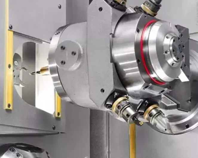
Technique 2: Tool Change Process Optimization — Reduced from “8 seconds/cycle” to “2 seconds/cycle”
1. Implement “Nearest Sorting” in Tool Magazine to Reduce Rotation Time
Principle: Arrange tools in machining sequence to avoid cross-area rotation (e.g., moving directly from Tool 1 to Tool 3 instead of 1→10→3).
Practical Implementation:
List part machining operations (e.g., Drilling → Milling → Boring → Tapping);
Assign corresponding tool numbers (Drill - No. 2, Milling - No. 3, Boring - No. 4, Tapping - No. 5);
Set “Sequential Retrieval” in the tool magazine management interface, reducing rotation time from 4 seconds/cycle to 1 second/cycle.
2. Tool presetting + tool length compensation eliminates in-machine tool setting time
Traditional issue: Each new tool requires manual setting (using edge finder or trial cutting) after installation, taking 3-5 minutes per tool;
Optimized Solution:
Use an offline tool presetter (e.g., Zoller V3) to measure tool length and radius, then input the compensation parameters into the machine tool;
After tool installation, directly call the compensation (G43 H...) without in-machine tool setting, saving 3 minutes per tool. With 10 tool changes per day, this saves 30 minutes.
3. Synchronize “Spindle Movement + Tool Magazine Rotation” to Overlap Tool Change Time
Traditional Process: Spindle returns to change point (2 sec) → Magazine rotates to select tool (3 sec) → Tool changer arm actuates (3 sec), total 8 sec;
Synchronized Optimization: Spindle moves to tool change point while tool magazine pre-rotates to select tool (2-second overlap), reducing total time to 6 seconds;
Compatible Systems: FANUC 0i-MF, Siemens 828D, etc., can enable synchronized tool changes via parameter settings (e.g., FANUC parameter 3190).
Technique 3: Cutting Parameter Optimization — Finding the “Efficiency vs. Tool Life” Balance Point
1. Match “Optimal Cutting Parameters” to Material Properties
Core Principle: Low speed with high torque for hard materials; high speed with light cutting for soft materials. Avoid “one-size-fits-all” parameters.
Common Material Parameter Table (with practical data):
Material Type | Tool Type | Cutting Speed v_c (m/min) | Feed Rate f (mm/rev) | Cutting Depth a_p (mm) | Single Part Machining Time Comparison (Before → After Optimization) |
Aluminum Alloy (6061) | Carbide TiAlN Coated | 300-400 | 0.2-0.3 | 1.5-3 | 5 min → 3 min |
Medium Carbon Steel (45#) | Carbide TiCN Coated | 120-150 | 0.15-0.2 | 1-2 | 8 min → 5 min |
Stainless Steel (304) | Carbide AlCrN Coated | 80-100 | 0.1-0.15 | 0.8-1.5 | 10 min → 7 min |
2. Enable “High Speed Machining (HSM) Parameters” to enhance feed efficiency
Applicable scenarios: Processes requiring high feed rates, such as mold cavity and surface machining;
Parameter settings:
FANUC systems: Enable G05.1 Q1 (AI priority control) to increase feed rate by 30% while preventing overcutting;
Siemens System: Enable “Dynamic Precision Control” (MD32200=1), increasing surface machining feed rates from 800 mm/min to 1000 mm/min.
3. Avoid “Over-machining”: Adjust Parameters According to Tolerance Requirements
Common Misconception: Using high-precision parameters (e.g., Ra 0.8μm) for all processes, resulting in excessively long finishing times;
Optimization:
Roughing: Prioritize efficiency (large a_p, high f), surface roughness Ra6.3μm is sufficient;
Semi-finishing: Transition to Ra3.2μm;
Finishing: Adjust to Ra1.6/0.8μm per drawing requirements, avoiding unnecessary precision waste, reducing finishing time by 20%.
Technique 4: Minimizing Empty Travel — Path Planning + Coordinate System Optimization
1. Plan toolpaths using “Clustering by Machining Zones”
Traditional issue: Tools traverse long distances between zones (e.g., machining left front hole → right rear hole → left rear hole), resulting in excessive empty travel;
Optimization: Process by “area grouping” (e.g., first machine all features in the left half → then the right half), reducing idle travel distance by 50%;
CAM Software Settings: Enable the “Area Sorting” function in UG/NX, selecting either “Concentric Arcs” or “Grid” sorting methods.
2. Multiple Coordinate Systems (G54/G55/G56) Reduce Workpiece Repositioning Time
Scenario: Machining 4 identical workpieces on a multi-station fixture;
Traditional Process: After machining 1 workpiece, manually re-align and reposition (3 minutes/cycle), totaling 12 minutes for 4 workpieces;
Optimization: Pre-set 4 coordinate systems (G54-G57), each assigned to one workpiece. After machining one, directly call the next coordinate system (G55) without repositioning, reducing total time to 2 minutes.
3. Reduce “Safety Height” to Minimize Z-Axis Idle Travel
Misconception: Uniformly setting safety height to Z50mm (far exceeding the highest workpiece height of Z15mm) results in excessive Z-axis idle travel distance;
Optimization: Set safety height to workpiece max height + 5mm (e.g., Z20mm). This reduces Z-axis travel by 60%, cutting single Z-axis idle time from 1.5 seconds to 0.6 seconds. Processing 100 parts daily saves 1.5 minutes.
Technique 5: Automation Tools — Reduce Manual Intervention, Enhance Continuous Machining Capability
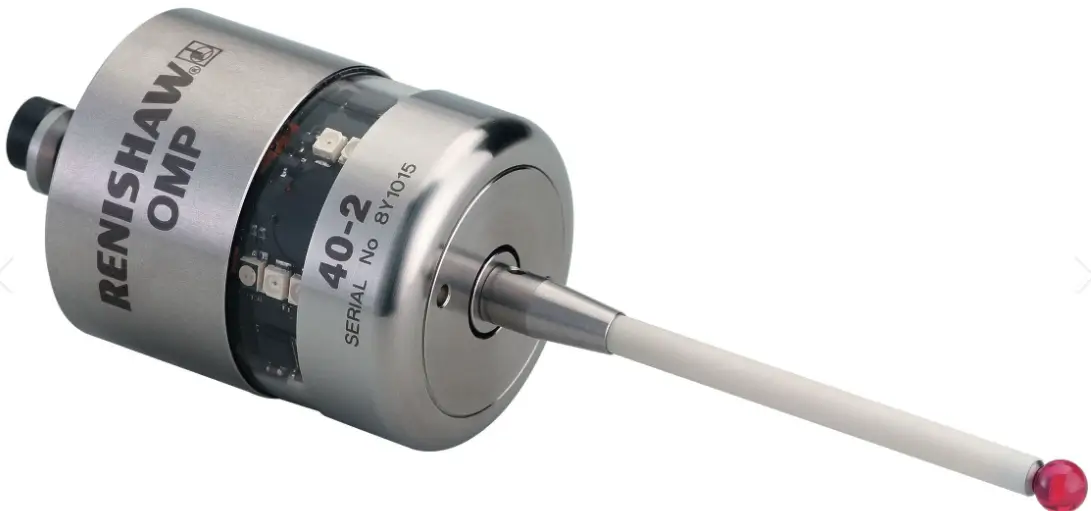
1. Workpiece Probe (e.g., Renishaw OMP40) Auto-Alignment + Dimensional Compensation
Traditional Issue: Manual workpiece alignment (using dial indicators) takes 2-3 minutes per piece with significant alignment error (±0.01mm);
Optimization: Enable automatic workpiece probe alignment. Process:
Probe contacts 3 reference surfaces on the workpiece, automatically calculates coordinate system deviation;
System automatically compensates for deviation (updates G54 parameters), reducing alignment time to 30 seconds per piece with error ≤0.003mm;
Benefit: Processing 50 pieces daily saves 75 minutes of manual alignment time.
2. Broken Tool Detection (G31) + Automatic Tool Change to Prevent Batch Scrap
Risk: Undetected tool breakage leading to continued machining, resulting in 10-20 scrap parts and 1-2 hours of rework time;
Solution: Insert broken tool detection command (G31) into the program:
plaintext
G90 G54 G00 X20 Y20 Z5
G31 Z-10 F100 (Tool contacts workpiece; no signal indicates breakage)
M03 S1500 (Automatic shutdown with alarm prompt for tool change upon breakage)
Effect: Immediate shutdown after breakage prevents batch scrap, reducing rework losses by over ¥10,000 monthly.
3. Automatic Chip Removal + Spindle Coolant, Reducing Downtime for Cleaning
Issue: Chip accumulation causes secondary cutting (accelerated tool wear), requiring manual shutdown for cleaning (10 minutes/session, 5 times daily);
Optimization:
- Enable spiral chip conveyor for automatic chip removal, eliminating manual cleaning;
Spindle-center coolant delivery (20-30 bar pressure) flushes chips from cutting zone while cooling tools;
Benefits: Reduces daily cleaning downtime by 50 minutes, extends tool life by 25%.
Practical Case: 40% Capacity Increase at Automotive Parts Factory
1. Original Issue
Machining 45# steel bearing housings (φ80mm×50mm), with a single-piece processing time of 12 minutes and a daily output of 50 pieces;
Efficiency bottlenecks: 35% idle travel time, tool change time of 8 seconds per operation (20 tool changes daily), and conservative cutting parameters (v_c=100m/min).
2. Optimization Measures
G-code optimization: Replaced angular interpolation with circular interpolation and utilized subroutine calls for multi-hole machining, reducing idle time from 4.2 minutes to 2.5 minutes;
Tool change improvements: Implemented tool magazine proximity sorting + pre-set tools, reducing change time from 8 seconds/change to 3 seconds/change, saving 1.7 minutes daily;
Cutting Parameters: Increased v_c to 140m/min, raised feed rate from 0.15mm/rev to 0.2mm/rev, reduced cutting time from 5.8 minutes to 4 minutes;
Automation Support: Installed workpiece probe, reduced alignment time from 3 minutes/piece to 0.5 minutes/piece.
3. Improvement Outcomes
Single-piece machining time reduced from 12 minutes to 7.2 minutes;
Daily output increased from 50 pieces to 84 pieces, achieving a 68% capacity boost (exceeding the 40% target);
Tool life extended from 8 hours to 10 hours, saving ¥2,000 in monthly tooling costs.
Common Efficiency Optimization Pitfalls and Avoidance Guide
1. Pitfall 1: Blindly Pursuing “High Speed” While Neglecting Tool Life
Issue: When machining 45# steel, increasing v_c to 200m/min reduced tool life from 8 hours to 2 hours. Frequent tool changes actually decreased efficiency.
Avoidance: Optimize parameters based on the premise “tool life ≥ 8 hours,” referencing the “Common Material Parameter Table” in this article, rather than solely pursuing high speeds.
2. Misconception 2: Optimizing programs while neglecting machine maintenance
Issue: After G-code optimization, spindle speed fluctuations exceeded 3%, resulting in lower-than-expected actual machining efficiency.
Solution: Check spindle bearing clearance monthly (≤0.002mm) and clean guideways/lead screws quarterly to ensure hardware performance matches optimized parameters.
3. Misconception 3: Small-batch production “isn't worth” optimization
Issue: Believing optimization yields low returns for small batches (e.g., 20 pieces daily) and abandoning improvements;
Solution: Small batches especially require optimizing tool change and alignment times (e.g., preset tools, multi-coordinate systems). After optimization, one workshop reduced single-piece processing time from 15 to 10 minutes, saving 1.7 hours daily and accumulating 34 hours monthly.
FAQ: Common Questions on Vertical Machining Center Efficiency Optimization
Q: Can G-code be manually optimized without high-end CAM software?
A: Yes! Focus on optimizing G00 paths (reducing safety height, using nearest-point movement) and using subroutine calls for repetitive features. Manual adjustments can boost efficiency by 10%-15% without complex software.
Q: Can synchronous tool changes be enabled on older vertical machining centers (e.g., FANUC 0i-MD)?
A: Most can. Contact the manufacturer to adjust parameters (e.g., set FANUC parameter 3190 to 1). This reduces tool change time by 20%-30% without hardware upgrades.
Q: Will optimizing parameters cause deformation when machining thin-walled parts?
A: No! Thin-walled parts benefit from “low feed + high speed + shallow cutting depth” (e.g., aluminum alloy thin-walls: v_c=350m/min, f=0.15mm/rev, a_p=0.5mm). This boosts efficiency while minimizing deformation from cutting forces.
Q: Will part accuracy decrease after efficiency optimization?
A: No! All techniques in this article are based on maintaining accuracy. For example, cutting parameter optimization references tool manufacturer recommendations, while G-code optimization prevents overcutting. This stability actually enhances accuracy consistency.
Conclusion
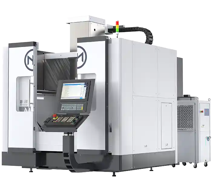
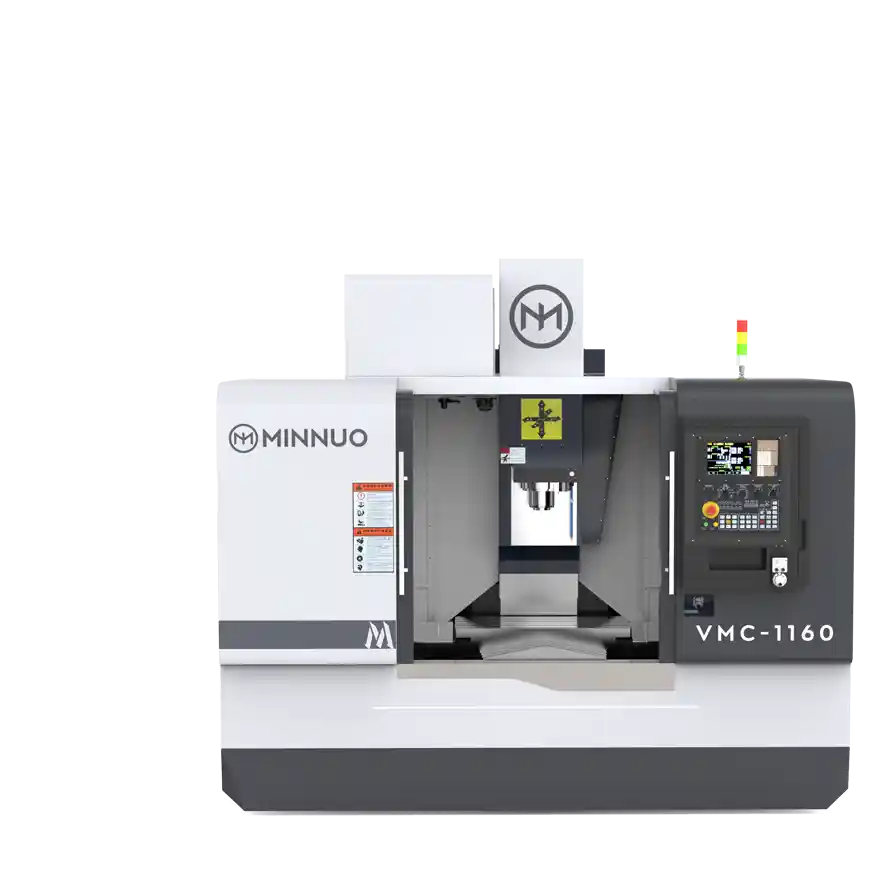
The core logic behind enhancing the efficiency of vertical machining centers lies in a dual-pronged approach: “reducing non-cutting time (idle travel, tool changes, alignment) + optimizing cutting time (parameters, paths).” Five practical techniques comprehensively minimize idle time—from software to hardware, and from manual to automated processes—ultimately achieving over 40% production capacity growth. MINNUO vertical machining centers are engineered from the ground up to align with this logic. Their CNC systems offer superior compatibility with G-code optimization, enabling efficient programming methods like arc interpolation and subroutine calls to deliver maximum performance. The tool-changing system employs a “proximity sorting + synchronized action” hardware design, natively supporting sub-second tool changes to lay the hardware foundation for efficiency gains.
If you're looking to boost your workshop's vertical machining efficiency, start today by selecting one commonly used part and optimizing its path using “Tip 4” in this article. You can also contact MINNUO's technical team to receive a complimentary efficiency diagnostic service tailored to your equipment. When performing weekly tool presetting or monthly production data analysis, MINNUO's nationwide service network and expert engineers will provide comprehensive support for your ongoing optimization efforts. This ensures your vertical machining center truly becomes the “high-efficiency production engine” of your workshop.
 Email
Email sales1: +86 15312799623