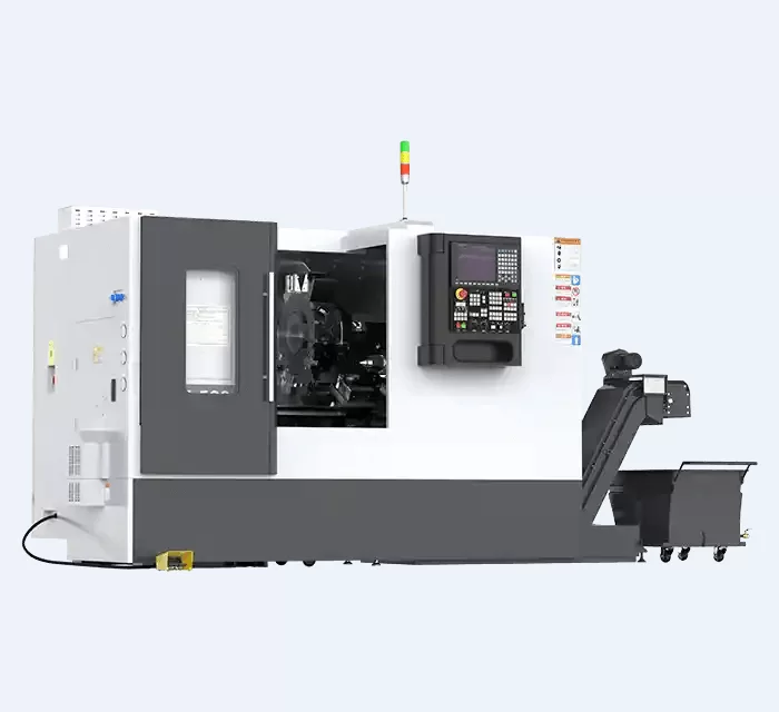
Optimization and Precise Control of Lathe Process Parameters: A Scientific Guide for Engineers
In the process workshop of a certain auto parts factory, Engineer Li is facing a thorny problem: the new batch of φ50mm shaft parts requires a surface roughness of Ra≤0.8μm. However, he adjusted the cutting speed and feed rate based on his experience and tried cutting 15 parts before barely meeting the standard. The material waste alone caused a loss of over 3,000 yuan. Worse still, two hours after mass production, the spindle experienced precision drift due to continuous heating. The diameter deviation of all 20 parts processed subsequently exceeded 0.02mm, and they had to be redone, resulting in a direct loss of nearly 40,000 yuan.
Such scenes are not uncommon in the manufacturing industry. Many factories still rely on "empiricism" to adjust the parameters of lathes. When confronted with problems such as thermal deformation of the spindle and fluctuations in surface roughness, they often fall into a vicious cycle of "trial cutting - scrapping - trial cutting again". In fact, the optimization of lathe process parameters does not require "blind trial and error", and precision control does not have to rely on high-end equipment worth millions.
This article breaks down the system into three core solutions - "orthogonal test + response surface method" for scientific parameter optimization, active compensation for spindle thermal deformation, and real-time accuracy control through online measurement. By combining practical cases and directly applicable formulas and processes, it helps engineers reduce trial cutting costs by 40% and keep the accuracy error rate within 3%. Enable ordinary lathes to stably output precision parts.
Understand the three core challenges of lathe parameter optimization and precision control
Before solving the problem, we need to first clarify exactly where the "precision bottleneck" that engineers often encounter comes from, so as to make targeted breakthroughs.
1. "Coupling effect" among parameters: A single adjustment is difficult to achieve global optimality
The three core parameters of lathe processing - cutting speed(v_c), feed rate (f), and cutting depth (a youdaoplaceholder0) - do not affect the processing quality in isolation, but have a coupling relationship that "affects the whole body with one hair" :
Increasing the cutting speed (for example, raising the cutting speed of 45# steel from 80m/min to 120m/min) can reduce the work hardening of the material. However, once it exceeds the critical value, the temperature at the tool tip will suddenly rise above 800℃, causing the tool coating to fail rapidly and the surface roughness to deteriorate from 0.8μm to 1.6μm instead.
Reducing the feed rate (such as from 0.2mm/rev to 0.08mm/rev) may seem to improve the surface finish, but it will cause the spindle to vibrate due to the uneven distribution of cutting force, ultimately leading to a 50% increase in the Ra value fluctuation range.
The traditional "single-factor adjustment method" (such as only adjusting the feed rate while ignoring the cutting speed) is like optimizing through a "glimpse of the leopard through a tube" approach, and it can never find the balance point of "excellent roughness, high efficiency and long tool life".
2. Spindle Thermal Deformation: The "Invisible Killer" of Precision
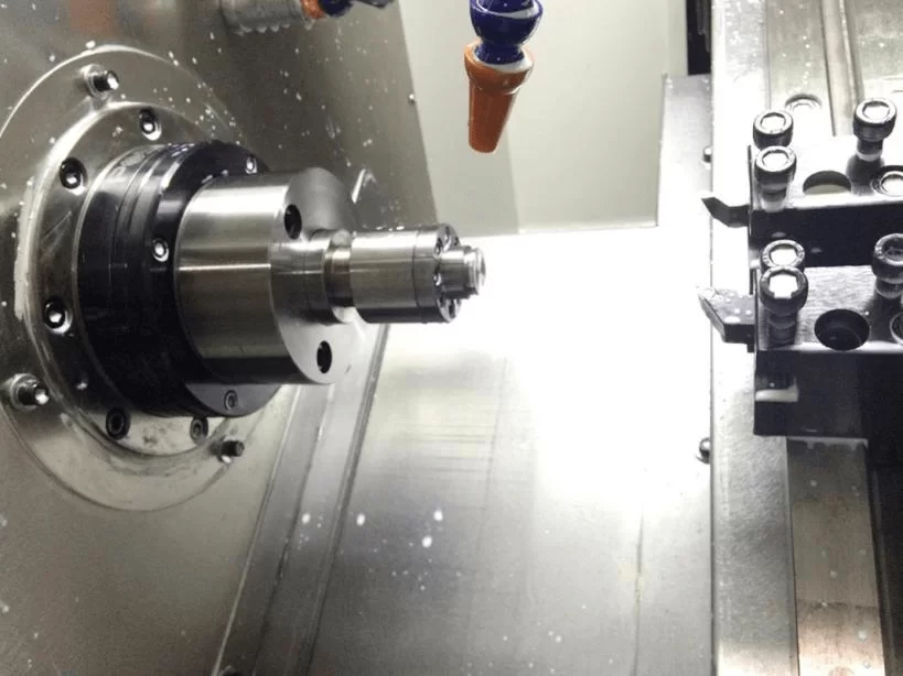
The spindle is the "power core" of a lathe, but its thermal deformation is often overlooked. When the main shaft is in operation, motor heating and bearing friction can cause the shaft system to elongate. A certain test data shows that after the BT40 main shaft has been running continuously for 2 hours, the elongation can reach 0.015mm. This minor deformation will directly cause two major problems:
"Dimensional deviation at both ends" of long shaft parts: For instance, when processing a 500mm long shaft part, the diameter is qualified in the cold state (φ50±0.005mm), but in the hot state, the diameter near the main shaft end becomes φ49.985mm, with a deviation of 0.015mm.
The perpendicularity of the end face exceeds the tolerance: During the processing of flange plates, thermal deformation can cause the end face runout to increase from 0.01mm to 0.03mm, which cannot meet the requirements of sealing assembly.
What is even more challenging is that there is no fixed pattern for thermal deformation: fluctuations in ambient temperature (±5℃) and changes in cutting depth (from 0.5mm to 2mm) will alter the rate of thermal deformation. The traditional "cold calibration before startup" method is completely unable to cover dynamic processing scenarios.
3. The "lag" of offline measurement: Once out of tolerance is detected, a batch of products have been scrapped
Most factories still adopt the quality control mode of "random inspection after processing" : after the parts are processed, the dimensions are checked with calipers or three-coordinate measuring machines. The fatal flaw of this approach is its "lag" - if it is found that the dimensions are out of tolerance, all 10 to 20 processed parts may be scrapped.
A more concealed risk lies in the fact that minor changes such as tool wear (for instance, the rear tool face wear exceeds 0.2mm) and fixture loosening can cause the surface roughness to continuously exceed the standard, but offline measurement cannot capture this in real time. By the time problems were detected during the inspection, defective products had accumulated and the cost of rework had increased significantly.
Core Plan 1: Scientifically optimize process parameters using the "orthogonal test + response surface method"
The essence of parameter optimization is to "find the optimal parameter combination with the fewest trial cuts." The combination of orthogonal experiments and response surface methods is precisely the scientific tool to achieve this goal, and even novice engineers can master it quickly.
Step 1: Clearly define the parameter range and evaluation indicators
First, based on the material characteristics of the workpiece, it is necessary to determine the reasonable adjustment range of the three core parameters to avoid tool damage or substandard quality caused by "parameter overstepping"
Workpiece material | Cutting speed v_c (m/min) | Feed rate f (mm/rev) | Cutting depth a youdaoplaceholder0 (mm) |
45# steel | 80-120. | 0.1-0.2 | 0.5-2.0 |
Titanium alloy | 30-50 | 0.05-0.1 | 0.3-1.0 |
Stainless steel | 60-80. | 0.08-0.15 | 0.5-1.5 |
The evaluation indicators should take into account the three major dimensions of "quality, efficiency and cost" :
Surface roughness (Ra) : Target ≤0.8μm (precision parts need ≤0.4μm);
Material removal rate (Q) : Q=1000v_cfa youdaoplaceholder1 (unit: mm³/min), reflecting processing efficiency;
Tool life (T) : Target ≥8 hours (with a subsequent tool face wear of 0.3mm as the failure standard).
Step 2: Orthogonal experimental design
Orthogonal experiments cover all parameter combinations with the fewest number of experiments through a "evenly dispersed and neatly comparable" table. Taking the processing of 45# steel as an example, the L9 (3⁴) orthogonal table (with 3 parameters and 3 levels, only 9 tests are required, which is 18 fewer than the full-factor test) is selected:
Test Number | Cutting speed v_c (m/min) | Feed rate f (mm/rev) | Cutting depth a youdaoplaceholder0 (mm) | Surface roughness Ra (μm | Tool life T (h |
1 | 80 | 0.1 | 0.5 | 1.0 | 10 |
2 | 80 | 0.15 | 1.2 | 1.2 | 8 |
3 | 80 | 0.2 | 2.0 | 1.5 | 6 |
4 | 100 | 0.1 | 1.2 | 0.8 | 9 |
5 | 100 | 0.15 | 2.0 | 1.1 | 7 |
6 | 100 | 0.2 | 0.5 | 1.3 | 8 |
7 | 120 | 0.1 | 2.0 | 0.9 | 6 |
8 | 120 | 0.15 | 0.5 | 1.0 | 7 |
9 | 120 | 0.2 | 1.2 | 1.4 | 5 |
Data processing techniques: Use "range analysis (R)" to determine the priority of parameter influence - calculate the average Ra value of each parameter at different levels, and then use "maximum - minimum value" to obtain the range. For example:
The range R of the feed rate is 1.5-0.8=0.7 (maximum), indicating that the feed rate has the greatest impact on Ra.
The range of cutting speed R=1.23-1.07=0.16, and the influence is secondary.
The range of cutting depth R=1.2-1.0=0.2 has the least impact.
Through range analysis, the "parameters to be adjusted first" (such as adjusting the feed rate first) can be quickly identified, avoiding blind trial and error.
Step 3: Find the "optimal parameter combination" using the response surface method
After determining the parameter influence weights through orthogonal experiments, the response surface method needs to be used to further narrow down the range and find the "balance point between quality and efficiency". The core principle is: Substitute the orthogonal experimental data into the quadratic regression model (such as Ra = a₀ + a₁v_c + a₂f + a₃a <s:1> + a₄v_cf + a₅v_ca <s:1> + a₆fa <e:1>), and visualize the relationship between the parameters and Ra through surface fitting.
Taking the processing of 45# steel as an example, the final optimal parameter combination obtained is:
Cutting speed v_c=105m/min;
Feed rate f=0.12mm/rev;
Cutting depth a youdaoplaceholder5 =1.0mm.
The processing effect at this point is as follows: Ra=0.75μm (meeting the standard), tool life 9.5 hours (exceeding the target by 18.75%), and material removal rate Q=1000×105×0.12×1.0= 12,600 mm³/min (efficiency increased by 20%).
Mandatory formula:
Cutting speed conversion: v_c = πdn/1000 (d = workpiece diameter mm, n = spindle speed r/min). For instance, when processing 45# steel with a diameter of 50mm, if v_c=105m/min, then the spindle speed n= (105×1000)/(3.14×50) ≈670r/min.
Material removal rate: Q = 1000v_cfa <e:1>, used to balance accuracy and efficiency (if efficiency is pursued, a <s:1> can be appropriately increased under the premise that Ra meets the standard).
Core Solution 2: Spindle Thermal Deformation Compensation - From "Passive Acceptance" to "Active Correction"
The precision drift caused by thermal deformation does not require the replacement of high-end spindles. It can be solved through the three-step method of "monitoring - modeling - compensation", which is cost-effective and highly effective.
Step 1: "Quantitative monitoring" of thermal deformation
First, data needs to be collected through sensors to establish the corresponding relationship of "temperature - deformation" :
Temperature sensor: Install one PT100 sensor each at the front end of the main shaft (close to the tool tip), the motor housing, and the middle of the guide rail (with an accuracy of ±0.1℃) to collect temperature data in real time (sampling frequency once per minute).
Displacement sensor: The elongation of the main shaft at different temperatures is measured by a laser interferometer (such as Renishaw XL-80). For instance, a certain test shows that for every 5℃ increase in temperature, the main shaft elongates by 0.008mm. When the temperature rises by 10℃, the elongation reaches 0.016mm.
Through this step, it can be clarified "how temperature changes affect the deformation of the main shaft", providing data support for subsequent compensation.
Step 2: Practical Compensation Algorithm (can be embedded in the machine tool PLC
It is recommended to adopt the "linear compensation model", which is simple in principle and easy to implement, and suitable for most lathes.
ΔL = k×ΔT + b
ΔL: Spindle elongation (mm);
ΔT: The difference between the current temperature and the cold state temperature (in ℃);
k: Proportionality coefficient (mm/℃, determined through actual measurement, for example, k=0.0016 for a certain CK6150 lathe);
b: Initial deviation (mm, systematic error in the cold state, such as b=0.002).
Example calculation: If the main shaft has been running for 2 hours and ΔT=10℃ (the current temperature is 10℃ higher than the cold state), then ΔL=0.0016×10 + 0.002=0.018mm. At this point, the machine tool PLC can automatically compensate -0.018mm in the Z-axis direction to offset the dimensional deviation caused by the elongation of the spindle.
To avoid the lag problem of "static compensation", it is recommended to update the temperature data every 5 minutes and dynamically adjust the compensation value - for example, when the ambient temperature rises sharply by 3℃, increase the compensation amount in time to ensure stable accuracy.
Step 3: Low-cost calibration Method (Suitable for old lathes
For old lathes without PLC interfaces, the "standard bar comparison method" can be used for manual compensation without the need to purchase additional equipment
Prepare a standard rod with an accuracy of no more than 0.001mm (such as φ50×300mm);
When the machine has been on for 0 hours (cold state), measure the diameter of the standard rod with a micrometer and record it as φ 50,000mm.
After 1 hour, 2 hours and 3 hours of startup, measure the diameter of the standard rod respectively and record the deviation (such as φ50.010mm after 1 hour and φ50.018mm after 2 hours).
Make a "time-compensation value" comparison table (such as 1-hour compensation -0.010mm, 2-hour compensation -0.018mm), stick it beside the machine tool, and the operator manually adjusts the Z-axis compensation value every hour.
Calibration should be carried out in a stable environment (with a temperature fluctuation within ±2℃), avoiding direct air conditioning or direct sunlight on the machine tool to prevent environmental temperature from interfering with the measurement results.
Core Solution 3: Online measurement Technology - Real-time interception of accuracy over-tolerance
Online measurement can transform quality control from "post-event inspection" to "in-process interception", avoiding batch scrapping and serving as the "last line of defense" for precision processing.
1.Selection of online measurement tools (matching as required)
Different measurement requirements require different tools to ensure a balance between accuracy and cost.
Measurement requirements | Recommended tools | Measurement accuracy | Applicable scenarios |
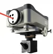
Dimensional accuracy (diameter, length) | Lathe probe (such as Blum Nano) | ≤0.0005 millimeters | Real-time measurement of shaft and disc parts |
Surface roughness | Online roughness meter (such as Mahr MarSurf | 0.001 microns or less | Precision parts (such as bearing rings |
Tool wear | Image sensor | ≤0.01 mm | Automatically detect chipping and wear of the blade tip |
For instance, when processing motor shafts, only a lathe probe (costing approximately 15,000 yuan) needs to be installed to achieve real-time size monitoring. If processing medical implants (such as artificial joints), an online roughness meter should be used to ensure that Ra≤0.4μm.
2. Real-time feedback process (Taking dimensional accuracy control as an example)
The core of online measurement is a closed-loop process of "measurement - compensation - verification", and the specific steps are as follows:
When the part is processed to the first key dimension (such as φ50mm), the machine tool automatically pauses, the measuring head extends and touches the surface of the workpiece, and records the actual dimension (such as φ50.015mm).
The system compares the measured value with the target value (φ50±0.005mm), calculates the compensation amount (X-axis compensation -0.0075mm), and automatically updates the processing program.
Continue processing the next part, trigger the probe again for measurement, and verify whether the dimensions meet the standards (such as φ50.002mm, which conforms to the tolerance);
If the dimensions of three consecutive parts remain stable, the measurement frequency can be adjusted (for example, measuring one out of every ten processed parts) to balance accuracy and efficiency.
Practical effect: After a certain motor shaft processing factory introduced online probes, the dimensional deviation rate dropped from 15% to 2.3%, reducing rework losses by 21,000 yuan per month, and the cost of purchasing probes could be recovered within six months.
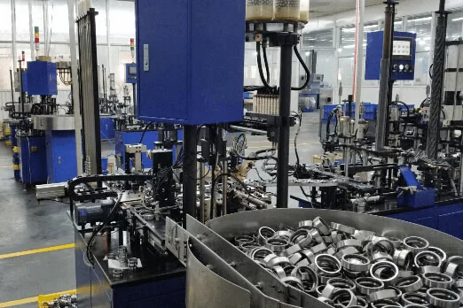
Practical Case: The "Precision Upgrade" Journey of a Certain Automotive Bearing Factory
The original question
A certain automotive bearing factory, when processing the outer rings of bearings (made of GCr15 material), is confronted with two major pain points
The surface roughness fluctuates greatly: The Ra value is between 1.0 and 1.8μm, with a pass rate of only 75%, and an additional polishing process is required.
The thermal deformation of the main shaft led to dimensional deviation: two hours after batch processing, the diameter deviation increased from 0.005mm to 0.018mm, resulting in a monthly rework loss of 28,000 yuan.
Optimization plan
Based on the three core solutions in this article, the factory has formulated targeted optimization strategies:
Parameter optimization: Through orthogonal experiments + response surface method, the optimal parameters were determined as v_c=95m/min, f=0.11mm/rev, a <s:1> =0.8mm;
Thermal deformation compensation: Deploy three temperature sensors at the front end of the main shaft, the motor, and the guide rail, and activate the linear compensation algorithm (k=0.0015mm/℃, b=0.002mm).
Online measurement: Install Blum probes, automatically measure once every 5 parts processed, and correct dimensional deviations in real time.
Improvement effect
Stable surface roughness: The Ra value is controlled between 0.7 and 0.9μm, the qualification rate is increased to 100%, the polishing process is eliminated, and the monthly labor cost is saved by 8,000 yuan.
Dimensional accuracy meets standards: Diameter deviation is always controlled within ±0.005mm, rework loss is reduced to 0, and 28,000 yuan is saved each month.
Tool life has been extended from the original 6 hours to 9 hours, and the cost of tool procurement has been reduced by 33%.
Overall, after optimization, the monthly cost is saved by 36,000 yuan, and the investment payback period is only four months.
FAQ: The 5 Most Concerned Questions of Process Engineers
1.Is orthogonal testing suitable for small-batch production (such as 50 pieces each time)?
Suitable! For small-batch production, the L4 (2³) orthogonal table (only 4 tests, 3 parameters, and 2 levels) can be selected, combined with the "parameter reuse" principle - for parts of the same material and specification, historical optimized parameters can be continued without the need for repeated tests. For instance, when processing 45# steel parts with a diameter of 50mm, the parameters can be determined after the first test of 4 pieces, and the subsequent 50 pieces can be directly applied. The trial cutting cost can be controlled within 2 pieces.
2. Without response surface method software (such as Minitab), how can I manually find the optimal parameters?
It can be achieved without software! Just use "range analysis + trend chart" :
Conduct range analysis on the orthogonal test data to determine the parameters with the greatest influence (such as feed rate);
Plot a line graph of the different levels of this parameter and the corresponding Ra values (with the feed rate on the X-axis and Ra on the Y-axis);
Find the lowest parameter range of Ra (such as feed rate 0.1-0.13mm/rev), and fine-tune it 2-3 times within this range (such as 0.11mm/rev, 0.12mm/rev), and the optimal value can be found.
3. How can thermal deformation compensation be achieved for old lathes (without PLC interfaces)?
Adopt the method of "manual compensation + regular calibration" :
Record the dimensional deviations of the main shaft after running for 1 hour, 2 hours and 3 hours, and make a "time-compensation value" comparison table.
The operator manually adjusts the Z-axis compensation value every hour according to the reference table (such as -0.01mm in 1 hour and -0.018mm in 2 hours).
Calibrate the compensation value with a standard rod once a week to ensure stable accuracy.
4. Will online probes increase processing time?
A single measurement only takes 3 to 5 seconds, having a minimal impact on overall efficiency. If you are concerned about the time cost, you can adopt the "batch measurement" strategy - for instance, measure each of the first three parts once. After confirming that the dimensions are stable, adjust to measure every 10 processed parts once. The overall processing time increases by no more than 2%, but it can avoid the risk of batch scrapping.
5. When processing difficult-to-machine materials (such as stainless steel), has the parameter optimization logic changed?
The core method remains unchanged, but the parameter range needs to be adjusted to prioritize ensuring tool life
Reduce the cutting speed by 30% : for instance, for stainless steel, v_c=60-80m/min (30% lower than 45# steel), to prevent the tool tip temperature from being too high;
Reduce the feed rate appropriately: for instance, from 0.2mm/rev to 0.08-0.15mm/rev to decrease the cutting force.
Moderate cutting depth: such as 0.5-1.5mm, to avoid excessive tool wear caused by multiple tool passes.
Conclusion
The core of optimizing and precisely controlling the process parameters of lathes is not "relying on high-end equipment", but "replacing empiricism with scientific methods" :
Through orthogonal experiments + response surface method, bid farewell to the vicious cycle of "trial cutting - scrapping", and find the optimal parameters with the fewest number of experiments.
Through the thermal deformation compensation of the main shaft, the "uncontrollable deformation" is transformed into "actively correctable deviation", breaking through the precision bottleneck.
Through online measurement, quality control is transformed from "post-event remediation" to "in-process interception", avoiding batch losses.
When these scientific methods are combined with the high-precision hardware and intelligent control system of MINNUO machine tools, the effect of process optimization can be twice as effective with half the effort - the thermal stability design of the spindle of MINNUO machine tools, the open parametric programming interface, and the high adaptability to online measurement equipment It provides solid hardware and technical support for the implementation of orthogonal tests, active compensation for thermal deformation, and closed-loop online measurement. Whether you are using a regular CNC lathe of MINNUO or a high-end precision model, as long as you master this set of methods, you can make the processing accuracy "controllable, repeatable and optimizable", and truly enhance the competitiveness of your products while reducing costs and improving efficiency.
 Email
Email sales1: +86 15312799623