What Are the Basic Structures of a Machine Tool?
Why do the precision and efficiency of the same workpiece vary so greatly when processed on different machine tools? What are the key components inside a machine tool, and how do they work together?
The core components of a machine tool include the bed, spindle, feed system, CNC system, and more. Each part plays a crucial role in the machining process.
Next, we will delve into the various structural modules of machine tools, helping you understand their functions and interrelationships, providing practical guidance for your selection and application.
I. Basic Support Structure:
1.Bed
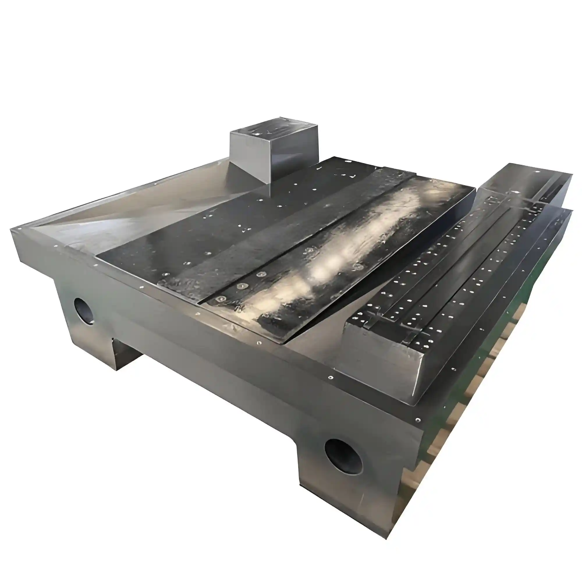
(Mineral castings for machine tool beds industry)
The bed serves as the main support of the machine tool, bearing the weight of all components and the load during machining.
Definition: The main support component of the machine tool, with all key parts installed on it.
Materials & Characteristics: Primarily made from gray cast iron (such as HT250/HT300) or welded steel structures, designed with internal ribs to enhance rigidity. The surface is processed with guide rails to direct moving parts.
Function: It bears the overall weight of the machine tool, the load of the workpiece, and cutting forces during machining. Its rigidity directly affects machining precision and stability.
2.Column and Crossbeam
The column and crossbeam together form the machine tool’s spatial frame, ensuring precise guidance of each motion axis.Application:
• In vertical machine tools (e.g., vertical machining centers), the column is fixed vertically to the bed, supporting the spindle box and providing vertical (Z-axis) motion rails.
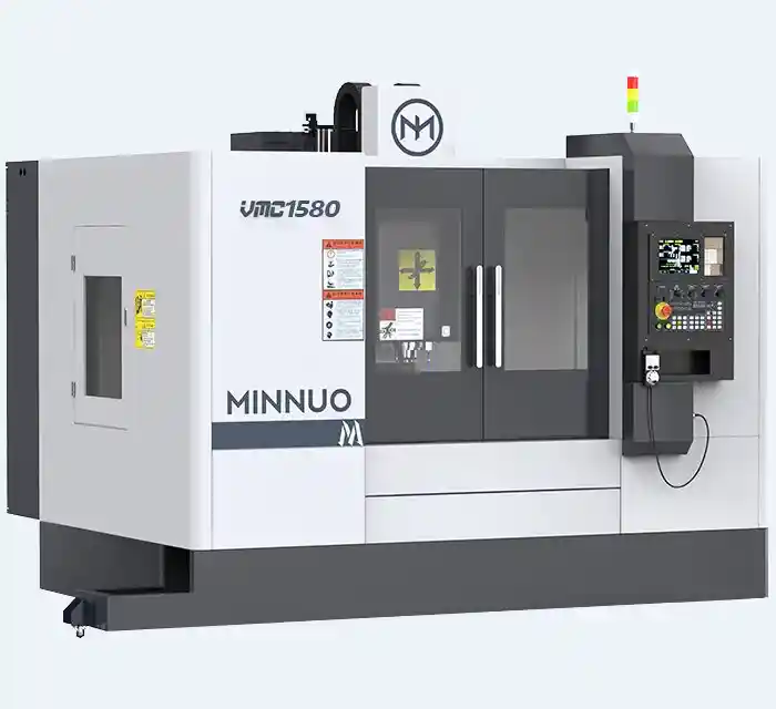
(vertical machine)
• In horizontal machine tools (e.g., gantry mills), the crossbeam spans the column and provides horizontal (Y-axis) motion rails.
(horizontal machine)
Function: They form the three-dimensional spatial structure of the machine tool, ensuring the verticality and parallelism of the motion axes.
3.Worktable
The worktable is the reference platform for workpiece positioning and clamping, directly affecting machining accuracy.Types & Functions:
• Fixed Type: Used to support large workpieces (e.g., worktables for floor-type boring machines), with T-slots or threaded holes for clamping.
• Movable Type: Supports linear motion (e.g., X/Y-axis worktables on CNC milling machines), with positioning accuracy up to ±0.005mm.
• Rotary Type: Includes indexing heads and CNC rotary tables, used for multi-surface machining or arc interpolation (indexing accuracy ±5″).
II. Motion Execution System:
4.Spindle System
The spindle system drives the rotation of the tool or workpiece, performing key machining functions like turning and milling.• Core Components: Spindle motor, spindle box, bearing group (such as angular contact ball bearings, tapered roller bearings), and tool interfaces (e.g., BT/HSK tool holders).
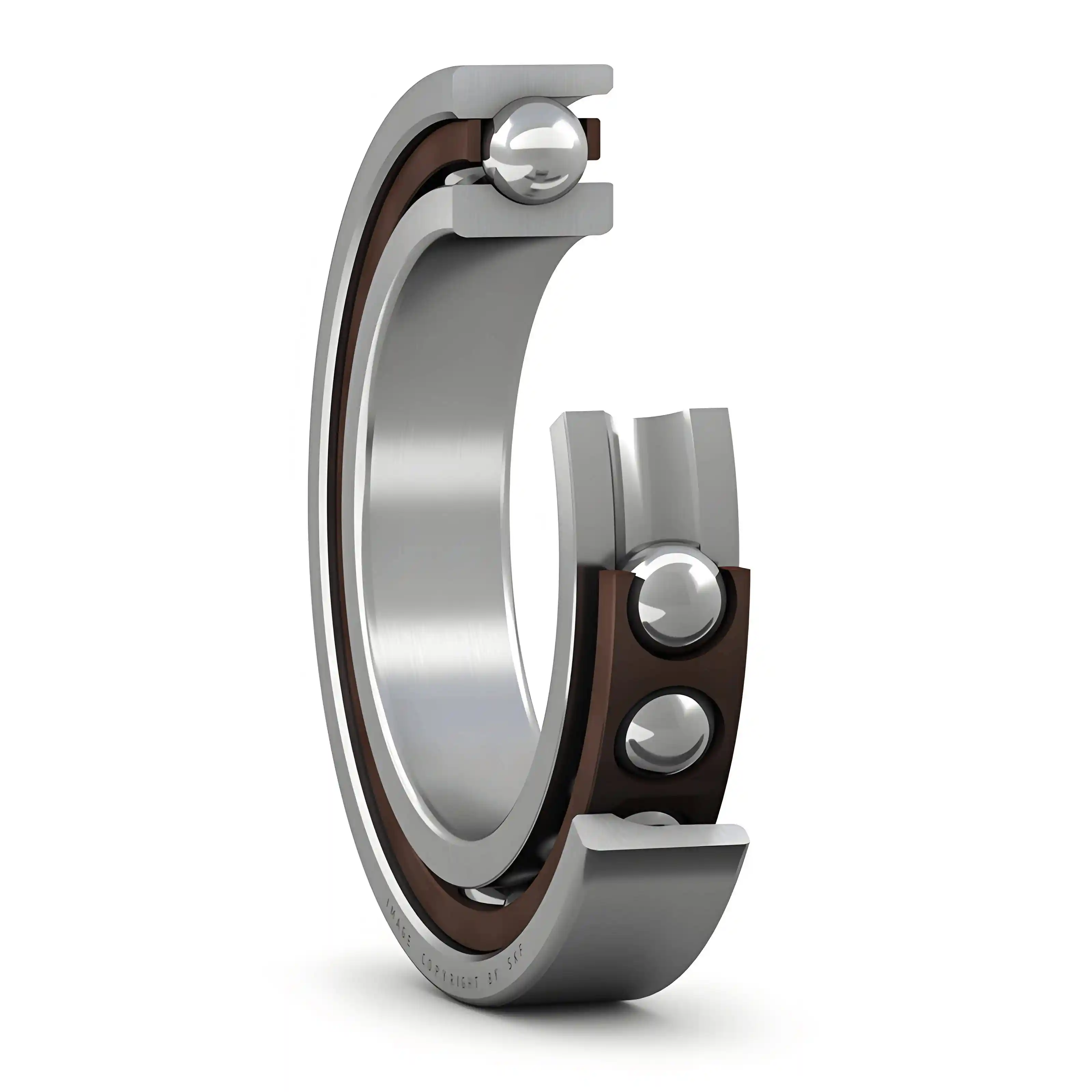
(angular contact ball bearings)
• Function: Drives the tool or workpiece to rotate and completes the main motion for operations like turning and milling. Speed ranges from low-speed heavy load (e.g., lathe spindle 50-2000 rpm) to high-speed precision (e.g., electric spindle 15,000-40,000 rpm).
5.Feed System
The feed system controls the relative motion trajectory between the tool and the workpiece, crucial for achieving precision machining.Composition & Principles:
• Drive Layer: Servo motors or stepper motors provide power.
• Transmission Layer: Ball screws (for high-precision scenarios, lead 5-20mm) or trapezoidal screws (for heavy-duty scenarios) convert rotational motion into linear motion.
• Guiding Layer: Linear guides (with rolling friction, accuracy ≤0.01mm/m) or plastic-coated sliding guides (for heavy-duty machine tools) ensure linear motion accuracy.
• Precision: Positioning accuracy can reach ±0.003mm (closed-loop system), and repeat positioning accuracy is ±0.002mm.
6.Speed Change System
The speed change system adjusts the spindle or feed speed according to machining requirements, ensuring cutting efficiency and quality.Types & Applications:
• Mechanical Speed Change: Achieved through gearboxes for multiple speed stages (e.g., the slip gear speed change in ordinary lathes).
• Electrical Speed Change: The CNC system directly controls the spindle motor for variable frequency speed control, without the need for mechanical shifting.
7.Tool Changer and Automatic Tool Change (ATC)
The tool changer and automatic tool change system enable the automatic switching of multiple tools, significantly improving batch machining efficiency.
Common Types:
• Disc Type Tool Changer: Capacity of 8-32 tools, tool change time of 4-8 seconds.
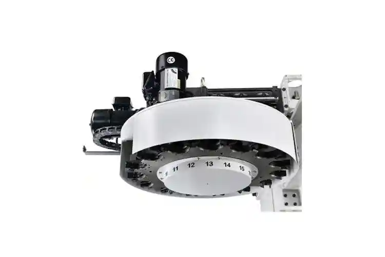
• Chain Type Tool Changer: Capacity of 32-120 tools, suitable for large machining centers.
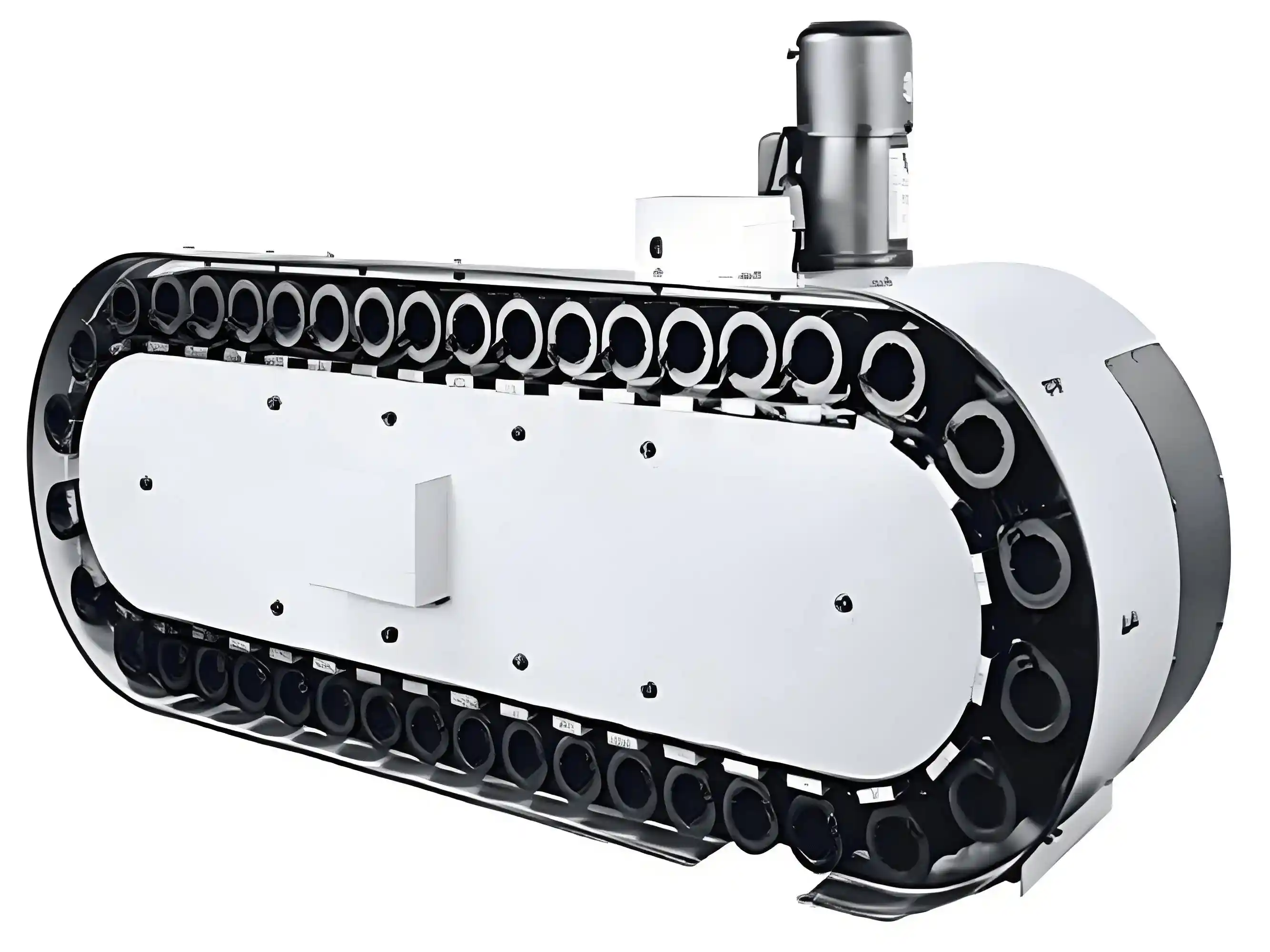
Function: Stores multiple tools and automatically changes them according to the program, improving batch machining efficiency.
III. Control and Detection Modules:
8.CNC System
The CNC system serves as the control core of the machine tool, parsing machining programs and coordinating the movement of each component.Core Functions: Parses machining programs (G-code), controls spindle speed, feed rate, and tool path, supports linear/arc interpolation, tool radius compensation, coordinate system transformation, etc.
Key Components: Controller (CPU), operator panel, servo drives, encoders (position feedback components).
9.Electrical Control System
The electrical control system manages the power supply and logic control of the machine tool, ensuring the orderly operation of components.Composition: Power distribution cabinet, circuit breakers, contactors, PLC (Programmable Logic Controller), responsible for motor start/stop, power distribution, and logic control.
10.Detection and Feedback Devices (Sensors)
Detection devices monitor the machine tool status in real-time, providing data support for precision control and fault warning.Types & Functions:
• Position Detection: Grating scales (for closed-loop systems, resolution 0.1μm), encoders (for semi-closed-loop systems, resolution 1μm).
• Status Monitoring: Temperature sensors (monitoring spindle bearing temperature rise), vibration sensors (pre-warning abnormal wear), tool breakage detection devices.
IV. Auxiliary Support Components:
11.Cooling System
The cooling system uses cutting fluid to lower machining temperatures and flush chips, ensuring stable performance of the tool and workpiece.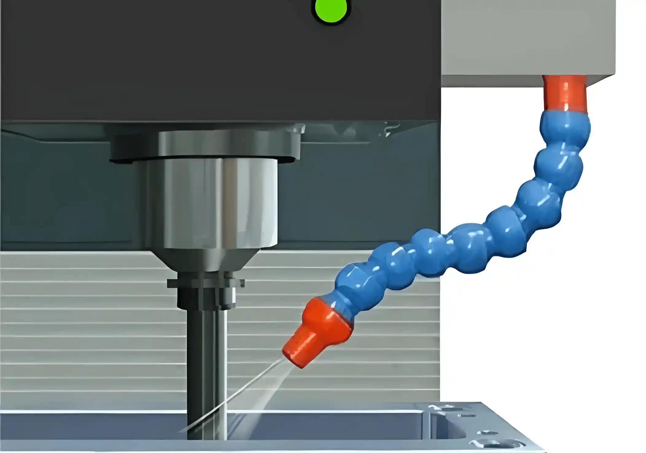
Components & Function: Cooling pumps (flow rate 25-100L/min), water tank, nozzles, filtration devices (magnetic filters for iron chips, paper filters for impurities), reducing tool/workpiece temperature and flushing chips.
12.Lubrication System
The lubrication system reduces friction between moving components, extending the machine tool’s service life and ensuring machining accuracy.Categories:
• Manual Lubrication: Regularly adds grease to guides and ball screws.
• Automatic Lubrication: Electric pump + progressive dispenser, providing oil to moving parts on a timed and measured basis (e.g., 5ml every 15 minutes).
13.Hydraulic and Pneumatic Systems
Hydraulic and pneumatic systems provide power support for the machine tool, adapting to different load requirements.Hydraulic System: Provides high-pressure oil to drive clamping chucks, spindle speed changes, and worktable locking, with a pressure range of 5-20MPa.
Pneumatic System: Uses compressed air for tool change blow-off, workpiece blow-off, with a working pressure of 0.4-0.7MPa.
14.Chip Removal and Protective Devices
Chip removal and protective devices ensure operator safety and maintain workshop cleanliness, being essential accessories for the machine tool.Chip Removal Types: Chain type (for steel chips), spiral type (for aluminum chips), magnetic type (for iron powder), supports continuous automatic chip removal.
Protective Devices: Steel plate shields (for impact protection), bellows-type covers (to prevent chip splashing), safety doors (with interlock, stop machine when the door is opened).
15.Fixtures and Accessories
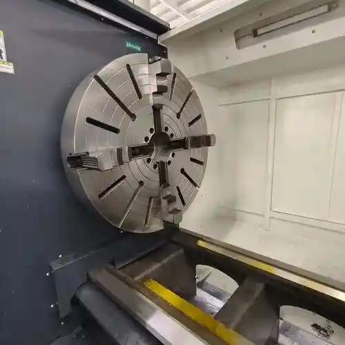
Fixtures and accessories are custom-made based on workpiece characteristics, key for precise clamping.General Fixtures: Vices (for medium and small workpieces), three-jaw chucks (for automatic centering, suitable for rotary parts), electromagnetic chucks (for ferromagnetic materials).
Custom Fixtures: Designed for workpieces’ specific shapes, such as composite fixtures for automotive parts machining.
V. Extended Structures:
16.Tailstock and Center Rest
Tailstocks and center rests are unique support components for lathes, used for the stable machining of long shaft workpieces.Application: Special parts for lathes, the tailstock supports the tail end of long shafts with a center point, and the center rest fixes the middle of the workpiece to reduce cutting deformation.
17.Pallet Changer
Pallet changers enable simultaneous workpiece clamping and machining, significantly improving efficiency for mass production.Function: In mass production, it allows workpiece clamping and machining to occur simultaneously, reducing downtime and improving productivity by 30%-50%.
18.Angle Head
Angle heads extend the machine tool’s machining directions, allowing for multi-angle cutting of complex parts.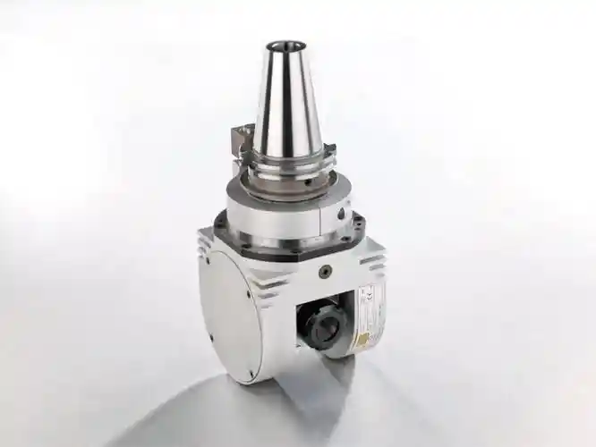
(universal angle heads)
Types: Right-angle heads (change machining direction by 90°), universal angle heads (support any angle adjustment), expanding the machine tool’s machining range.
VI. The Core Logic of Structural Coordination:
The efficient operation of a machine tool relies on the precision matching and dynamic response of each module:
• Rigid Transmission Chain: Bed → Guideways → Ball screws → Spindle → Tool; any link with insufficient rigidity will lead to vibration or precision loss.
• Thermal Management Design: Heat generated by the spindle motor and guideways must be controlled through the cooling system and structural heat dissipation (e.g., symmetric layouts) to avoid thermal deformation.
• Control Feedback Loop: CNC system issues commands → Servo motor executes → Sensors provide feedback → Error correction, forming a complete automated control loop.
Summary:
By understanding the functional positioning and coordination mechanisms of each component, you can scientifically select the machine tool configuration based on the material being processed (such as steel/aluminum/composite materials), process requirements (precision/efficiency), and production scale, achieving the precise implementation of your machining goals.
If you have any questions about machine tool structure, selection, or application, feel free to contact us at Minnuo. Our professional technical team will provide detailed answers and personalized solutions to help your production needs succeed efficiently.
 Email
Email sales1: +86 15312799623