



How to Calculate Thread Pitch: Formulas, Examples & Measurement
Thread pitch is an important parameter in mechanical design, CNC machining, and threaded component manufacturing. It determines the distance between adjacent threads and affects the compatibility of bolts, nuts, screws, and other threaded components.
To calculate thread pitch, divide the measured axial length by the number of complete thread intervals. For imperial threads, divide 25.4 by the threads per inch (TPI) to obtain the pitch in millimeters.
The two main formulas are:
Metric Thread Pitch (mm) = Measured Length (mm) ÷ Number of Pitch Intervals
Imperial Thread Pitch (mm) = 25.4 ÷ Threads Per Inch (TPI)
This guide explains how to calculate metric and imperial thread pitch, measure unknown threads using common tools, and understand the relationship between pitch, lead, and thread starts.
1. Calculating Thread Pitch
Thread pitch calculations depend on whether the thread follows metric or imperial specifications. Both methods determine the axial distance between corresponding points on adjacent threads.
1.1 Metric Thread Pitch Calculation
For metric threads, pitch is measured in millimeters (mm).
Formula:
Thread Pitch (mm) = Measured Length (mm) ÷ Number of Complete Pitch Intervals
Where:
- Thread Pitch: Distance between adjacent thread forms
- Measured Length: Axial distance measured across several thread intervals
- Pitch Intervals: Number of complete spaces between corresponding thread crests
Example:
Suppose the measured axial distance from the first thread crest to the third thread crest is 3 mm.
There are two complete pitch intervals between these three crests.
Thread Pitch = 3 ÷ 2 = 1.5 mm
Result: The thread pitch is 1.5 mm.
When measuring thread pitch, count the intervals between thread crests rather than the number of crests themselves.
Measuring across several complete pitch intervals can help reduce measurement errors.
1.2 Imperial Thread Pitch Calculation (TPI)
Imperial threads are commonly specified using threads per inch (TPI).
TPI indicates the number of thread pitches within one inch of axial length.
Formulas:
Thread Pitch (inches) = 1 ÷ TPI
Thread Pitch (mm) = 25.4 ÷ TPI
Example:
A bolt has 20 threads per inch.
Thread Pitch (inches) = 1 ÷ 20 = 0.05 inches
Converting the result to millimeters:
Thread Pitch (mm) = 25.4 ÷ 20 = 1.27 mm
Result: A 20 TPI thread has a pitch of 0.05 inches, or 1.27 mm.
A higher TPI value indicates finer thread spacing, while a lower TPI value indicates coarser thread spacing.
1.3 Common Thread Pitch Calculation Examples
The following examples demonstrate how to calculate or verify pitch using common thread specifications.
Example 1: M12 × 1.75 Metric Thread
An M12 × 1.75 bolt has:
- Nominal major diameter: 12 mm
- Thread pitch: 1.75 mm
The pitch is already specified in the thread designation.
It can also be verified by measuring several complete pitch intervals.
For example, the theoretical length across four pitch intervals is:
Measured Length = Thread Pitch × Number of Pitch Intervals
Measured Length = 1.75 × 4 = 7 mm
Therefore:
Thread Pitch = 7 ÷ 4 = 1.75 mm
Result: The thread pitch is 1.75 mm.
Example 2: 1/4-20 Imperial Thread
A 1/4-20 thread has:
- Nominal major diameter: 1/4 inch
- Threads per inch: 20 TPI
Using the conversion formula:
Thread Pitch = 25.4 ÷ 20 = 1.27 mm
Result: The thread pitch is 1.27 mm.
Example 3: M8 × 1.25 Metric Thread
An M8 × 1.25 thread has a nominal major diameter of 8 mm and a pitch of 1.25 mm.
If the measurement spans four complete pitch intervals:
Measured Length = 1.25 × 4 = 5 mm
Therefore:
Thread Pitch = 5 ÷ 4 = 1.25 mm
Result: The thread pitch is 1.25 mm.
1.4 Using a Thread Pitch Calculator

For more complex thread calculations, software tools such as G-Wizard can assist with determining thread dimensions and machining parameters.
Users can enter specifications such as:
- Thread type
- Major diameter
- Thread pitch or TPI
- Applicable thread standard
Depending on the software's capabilities, it can calculate related thread dimensions and machining parameters.
However, basic thread pitch calculations can be completed using the formulas above. Specialized software is more useful when additional thread geometry or machining requirements must be considered.
2. Measuring Thread Pitch
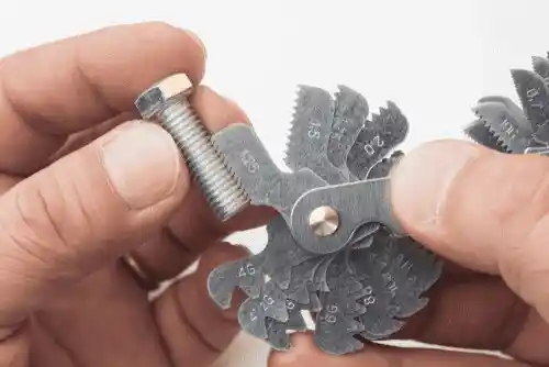
Accurate thread pitch measurement is essential for identifying unknown threads and ensuring compatibility between threaded components.
Common measurement tools include rulers, calipers, and thread pitch gauges.
2.1 Using a Ruler or Caliper
A ruler or caliper provides a simple way to estimate thread pitch, particularly when the threads are large enough to measure clearly.
Using a Ruler
Select two thread crests separated by several complete pitch intervals. Measure the axial distance between them and divide it by the number of intervals.
For example, if four complete pitch intervals measure 5 mm:
Thread Pitch = 5 ÷ 4 = 1.25 mm
The measured pitch is 1.25 mm.
This method works for basic measurements but may be less reliable for fine threads.
Using a Caliper
A caliper can measure the major diameter of an external thread and, where accessible, estimate the axial distance between thread crests.
When measuring pitch, select corresponding points separated by several complete intervals to reduce measurement errors.
Calipers also help identify thread specifications by measuring their nominal diameter.
However, thread diameter alone cannot determine thread pitch. The same nominal diameter may be available with different coarse or fine thread specifications.
Measurement Limitations
Rulers and calipers are useful for preliminary thread identification. For small threads or precision inspection, specialized tools may be necessary.
2.2 Using a Thread Pitch Gauge
A thread pitch gauge is one of the most convenient tools for identifying nominal thread pitch.
It consists of multiple blades with different thread profiles, each marked with its corresponding pitch or TPI value.
How to Use a Thread Pitch Gauge
Step 1: Select the Correct Gauge
Choose a metric or imperial thread pitch gauge according to the thread specification.
Step 2: Match the Threads
Place the gauge blade against the thread and check whether its teeth align with the thread grooves.
Step 3: Check the Fit
If the blade does not fit correctly, try another size until the gauge profile matches the thread without noticeable gaps.
Step 4: Read the Pitch
Read the marked pitch value in millimeters or the corresponding TPI value.
Advantages of Thread Pitch Gauges
- Quick identification of thread pitch
- Simple operation
- Suitable for many internal and external threads
- Useful in manufacturing, maintenance, and equipment inspection
A thread pitch gauge is effective for identifying nominal thread spacing. However, it cannot independently verify all thread dimensions or manufacturing tolerances.
3. Understanding Thread Pitch
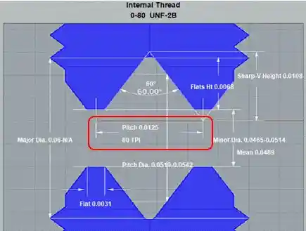
Thread pitch refers to the axial distance between corresponding points on two adjacent thread forms, commonly measured between neighboring thread crests.
It is an important parameter for identifying thread specifications and determining compatibility between threaded components.
3.1 Metric vs. Imperial Thread Pitch
Metric Thread Pitch
Metric threads use millimeters to express pitch.
For example:
M8 × 1.25
- M8 indicates a nominal major diameter of 8 mm.
- 1.25 indicates a thread pitch of 1.25 mm.
Metric threads are widely used in mechanical equipment, automotive components, and industrial manufacturing.
Imperial Thread Pitch
Imperial threads are commonly specified using threads per inch.
For example:
1/4-20 UNC
- 1/4 indicates a nominal major diameter of 1/4 inch.
- 20 indicates 20 threads per inch.
- UNC identifies the Unified National Coarse thread series.
Within the same measurement system, a higher TPI value indicates a smaller pitch, while a lower TPI value indicates a larger pitch.
3.2 External vs. Internal Threads
Threads can also be classified according to their position on a component.
External Threads
External threads are formed on the outside surfaces of components such as bolts, screws, and studs.
Common manufacturing methods include thread cutting, rolling, and other suitable forming processes.
Internal Threads
Internal threads are formed inside holes or components such as nuts and threaded housings.
Common manufacturing methods include tapping, thread milling, and internal threading.
Both internal and external threads require compatible pitch, diameter, profile, and tolerance specifications to ensure proper engagement.
4. Thread Characteristics and Terminology
Understanding the main thread dimensions helps distinguish thread pitch from other geometric parameters.
4.1 Major Diameter
The major diameter is the largest diameter of a threaded profile.
For external threads, it corresponds to the diameter measured across the thread crests.
For example:
- M8: Nominal major diameter of 8 mm
- 1/4-20: Nominal major diameter of 1/4 inch
Major diameter is used to identify the basic thread size and determine compatibility between threaded components.
4.2 Minor Diameter
The minor diameter is the smallest diameter of a threaded profile.
For external threads, it corresponds to the diameter at the thread roots.
For internal threads, it corresponds to the diameter at the internal thread crests.
Minor diameter influences thread geometry and is an important parameter in thread manufacturing and inspection.
4.3 Pitch Diameter
The pitch diameter is the diameter of an imaginary cylinder that intersects the thread profile where the width of the thread material equals the width of the adjacent groove.
Pitch diameter is an important dimension when evaluating thread fit and dimensional tolerances.
However, pitch diameter and thread pitch are different measurements.
- Thread Pitch: Axial distance between adjacent corresponding thread points
- Pitch Diameter: A diameter used to evaluate thread geometry and fit
For basic thread pitch calculations, it is usually unnecessary to calculate the major, minor, or pitch diameter first.
5. Lead Screws and Thread Starts
Lead screws and multi-start threads are widely used in mechanical transmission systems, including CNC equipment, linear actuators, and other motion-control devices.
In these applications, it is important to distinguish between thread pitch and lead.
5.1 What Are Lead Screws?
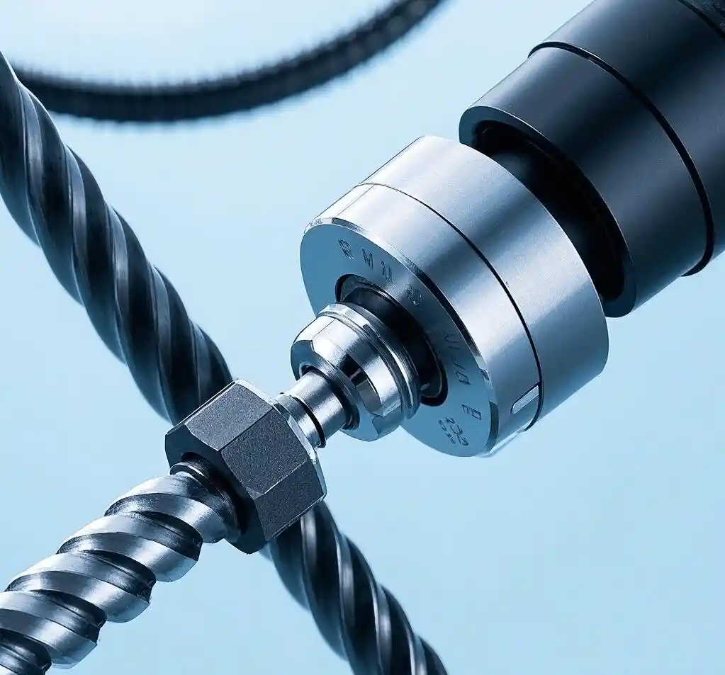
A lead screw is a mechanical transmission component that converts rotational motion into linear movement through a threaded interface.
Lead screws are commonly used in mechanical positioning systems, linear actuators, and industrial equipment.
Common designs include trapezoidal-thread lead screws, Acme-thread lead screws, and other configurations suited to specific load and motion requirements.
Lead refers to the axial distance traveled during one complete revolution.
For a single-start thread:
Lead = Thread Pitch
For example, if a single-start lead screw has a pitch of 5 mm, one complete revolution produces 5 mm of axial movement relative to its mating nut, assuming normal engagement without slip.
5.2 Thread Starts and Their Relationship to Pitch
Thread starts refer to the number of independent helical threads formed around a screw.
Single-Start Threads
A single-start thread has one continuous helix.
Its lead equals its pitch.
For example, if the thread pitch is 2 mm:
Lead = 2 × 1 = 2 mm
Multi-Start Threads
A multi-start thread contains two or more independent helices.
The lead is calculated by multiplying the thread pitch by the number of starts.
Formula:
Lead = Thread Pitch × Number of Starts
Conversely:
Thread Pitch = Lead ÷ Number of Starts
Example: Four-Start Thread
Suppose a four-start thread has a pitch of 2 mm.
Lead = 2 × 4 = 8 mm
This means the threaded mechanism advances 8 mm per complete revolution.
If the lead is 8 mm and the thread has four starts:
Thread Pitch = 8 ÷ 4 = 2 mm
Result: The thread pitch is 2 mm, and the lead is 8 mm.
Multi-start threads provide greater axial travel per revolution at the same pitch. However, actual positioning accuracy and load capacity depend on thread geometry, manufacturing accuracy, and the overall transmission system.
6. Tips for Choosing the Right Thread Pitch
Selecting the correct thread pitch requires consideration of application requirements, loading conditions, accuracy, material properties, and operating environment.
Different threaded components have different design objectives, so performance cannot be judged by pitch alone.
6.1 Application Requirements
Load Capacity
Both coarse and fine threads can provide reliable connections when properly designed.
Coarse threads are often preferred in applications requiring greater resistance to thread damage or frequent assembly and disassembly.
Fine threads may offer advantages in certain fastening and precision-adjustment applications.
Actual connection strength also depends on material properties, thread engagement length, and overall joint design.
Precision
In positioning and adjustment mechanisms, a smaller lead allows less axial movement per revolution.
However, positioning accuracy is not determined by pitch alone. Manufacturing errors, backlash, and structural rigidity must also be considered.
Movement Speed
In screw-driven motion systems, greater lead produces more axial travel per revolution at the same rotational speed.
Therefore, movement calculations should use thread lead rather than pitch alone when multi-start threads are involved.
Operating Environment
Threaded components exposed to vibration, moisture, chemicals, or repeated loading require suitable materials and connection designs.
Locking methods, corrosion protection, and maintenance practices may be more important than pitch alone.
6.2 Material Considerations

Hard Materials
Steel and other high-strength materials can accommodate different thread pitches depending on load requirements, engagement length, and manufacturing methods.
Soft Materials
For softer materials such as aluminum and some plastics, coarse threads are often used to reduce the risk of thread damage or stripping.
However, the appropriate thread specification depends on the complete application.
Wear and Lubrication
Moving threaded components may require lubrication to reduce friction and wear.
Thread geometry, material selection, and surface treatment also affect service life.
Corrosion Resistance
Threaded components operating in corrosive environments should use suitable materials and protective finishes.
Corrosion resistance primarily depends on material properties and environmental compatibility rather than thread pitch alone.
Conclusion
Calculating thread pitch is essential for identifying thread specifications, selecting compatible components, and preparing CNC threading operations.
The main formulas are:
Metric Thread Pitch (mm) = Measured Length (mm) ÷ Number of Complete Pitch Intervals
Imperial Thread Pitch (mm) = 25.4 ÷ TPI
Multi-Start Thread Pitch = Lead ÷ Number of Starts
A ruler or caliper can provide an initial pitch measurement, while a thread pitch gauge offers a convenient way to identify nominal thread spacing.
Understanding the differences between pitch, lead, and other thread dimensions helps prevent errors during mechanical design, equipment maintenance, and thread machining.
For more information about CNC threading applications and machining equipment, contact MINNUO for technical assistance.
 Email
 sales1: +86 15312799623