



CNC EDM vs. Laser Drilling for Automotive Injector and Valve Microholes
Choose dedicated micro-EDM for thick, angled, tapered, or post-heat-treatment microholes. Evaluate laser drilling first for high-volume thin-wall holes. For high-volume injector nozzles, also compare laser pre-drilling followed by EDM finishing. A general-purpose CNC hole popper is not automatically suitable for precision injector holes.
Why Automotive Microhole Procurement Cannot Be Based on Speed Alone
For fuel injector nozzles, control valves, and precision metering components, “the hole is open” is not an adequate acceptance criterion. Three issues determine actual performance and production cost.
- A hole can meet its diameter specification and still produce unstable flow. Inlet radius, outlet diameter, hole length, taper, wall texture, and spatial angle affect discharge coefficient, cavitation, and spray formation.
- A successful sample does not prove process stability. EDM is affected by electrode wear, short-circuit retraction, dielectric contamination, and electrode-change downtime. Laser drilling is affected by focus drift, protective-window contamination, recast material, and assist-gas variation.
- Fast drilling does not guarantee a low cost per accepted hole. The calculation must include electrodes or optical consumables, cleaning, flow sorting, destructive inspection, rework, and scrap.
Diesel common-rail systems can operate at up to 2,500 bar, while gasoline direct-injection systems can reach 350 bar. Microcracks, abnormal recast layers, and geometric errors therefore cannot be treated as cosmetic defects. Bosch diesel common-rail system, Bosch gasoline direct injection
The relevant purchasing metric is the cost per accepted hole:

Machine price or a single demonstration cycle does not represent production economics.
CNC EDM, Laser, and Hybrid Microhole Drilling Compared
The following values come from specific machines or research conditions. They establish technical boundaries but are not universal performance guarantees.
| Parameter | Dedicated micro-EDM | Water-jet-guided microsecond laser | Femtosecond laser | Laser pre-drilling + EDM finishing |
|---|---|---|---|---|
| Primary application | Thick walls, angled holes, tapers, hardened steel | Thin-wall spray holes, high hole counts | Heat-sensitive precision microholes | High-volume, high-quality injector nozzles |
| Published diameter reference | φ140–300 μm | φ180 μm test holes | φ150–200 μm-class GDI research | Below φ145 μm in published research |
| Published thickness reference | Wall thickness above 1 mm | 0.30 mm specimen | Approximately 0.25–0.35 mm specimens | Depends on pilot-hole and finishing allowance |
| Dimensional result | ±2 μm on a dedicated research system | Less than 1 μm variation across 25 holes | Depends on spot size and scanning path | Depends on alignment between processes |
| Hole-wall result | Rq approximately 220–560 nm | Rq approximately 150 nm | Rq approximately 50–100 nm | Approaches the final EDM-finished condition |
| Edge characteristics | Approximately 3–4 μm radius in one study | Burrs observed on specific specimens | Less than 1 μm radius in one study | Controlled by finishing allowance |
| Electrode or source | Fine tungsten, tungsten-copper, or carbide electrodes | Microsecond source with water jet | Approximately 0.01–0.20 kW source class | Requires both process systems |
| Motion control | Electrode rotation, vibration, or orbital motion | Beam scanning and workpiece positioning | Trepanning or helical scanning | Precision alignment between processes |
| Utilities | Dielectric flow in m³/h, conductivity, temperature | Water pressure in MPa and flow in m³/h | Gas pressure in MPa and flow in m³/h | Combined requirements of both systems |
| Main risks | Electrode wear, recast layer, taper instability | Burrs, thermal effects, nozzle maintenance | High investment, narrow process window | Alignment error and two-stage logistics |
| Priority condition | Geometry and aspect ratio dominate | Thin-wall throughput dominates | Hole-wall quality dominates | Throughput and final quality are both constrained |
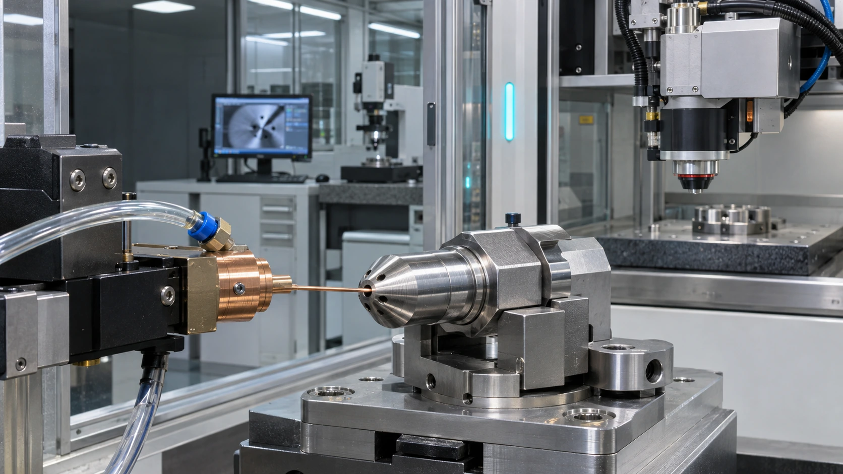
Conceptual comparison of internally flushed micro-EDM and laser microhole drilling. Actual equipment geometry and process parameters vary by application.
Published ultrashort-pulse laser sources cover approximately 10–200 W, or 0.01–0.20 kW. Source power alone, however, cannot be converted directly into injector-hole cycle time. TRUMPF TruMicro 2000, TRUMPF TruMicro 6000
General Hole Popper or Dedicated Injector Micro-EDM?
Fuel injector holes in the φ140–200 μm range generally require dedicated micro-EDM capability. Maximum spindle speed alone does not establish suitability.
General-purpose CNC hole EDM machines are commonly used for die-start holes and larger deep holes. The Sodick K3HS, for example, has a published electrode range of 0.25–3.0 mm and a maximum spindle speed of 1,000 rpm. Those specifications do not demonstrate stable capability for φ140–200 μm injector holes. Sodick K3HS specifications
Dedicated injector micro-EDM normally requires:
- Electrode capability below 100 μm;
- Electrode orbiting, path generation, or taper-forming motion;
- Online electrode-wear compensation;
- A low-energy pulse generator;
- Multi-axis angular and focal-position control;
- Breakthrough detection, automatic electrode handling, and production automation.
The Sodick K3BL has a published machining range beginning at approximately 80 μm and includes a 37 μm hole sample in cemented carbide. That sample required 6–8 minutes per hole, so it cannot be treated as an automotive injector production-cycle benchmark. Sodick K3BL specifications and samples
A useful request for quotation must state:
- Minimum electrode diameter;
- Target hole diameter and tolerance;
- Inlet and outlet diameters;
- Actual hole length;
- Material and heat-treatment hardness;
- Spatial angle;
- Permitted recast-layer condition;
- Required annual volume of accepted holes.
The phrase “CNC EDM drilling machine” alone is insufficient for a technically comparable quotation.
Which K-Factor Definition Should Be Used?
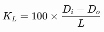
The drawing must define the K-factor formula and the inlet-to-outlet direction. A requirement such as “K = 2” is not independently enforceable.
Fuel injector microhole geometry showing inlet diameter Di, outlet diameter Do, hole length L, fuel-flow direction, and a magnified hole-wall inspection area.
At least two K-factor definitions appear in injector literature.
Length-normalized definition:
Ten-micrometer-normalized definition:
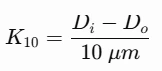
Where:
- Di is the hole inlet diameter in the fuel-flow direction;
- Do is the outlet diameter;
- L is the actual hole length.
When L=1,000 μm, the two definitions produce the same numerical result. They are not directly comparable when the hole length differs from 1 mm.
A dedicated micro-EDM study using the length-normalized definition reported:
- Hole diameters of φ140–300 μm;
- Wall thickness above 1 mm;
- Taper angles of 0–1.3°;
- Dimensional accuracy of ±2 μm;
- Spatial angular error below 0.2°;
- Machining feed of 1.5 mm/min.
These are results from a dedicated research system under defined conditions, not default capabilities of general-purpose hole EDM machines. Micro-EDM injector-hole research
The purchasing drawing should specify:
- Whether KL or K10 is used;
- Actual fuel-flow direction;
- Inlet and outlet measurement planes;
- Whether inlet rounding is included in the diameter;
- Permitted K-factor tolerance;
- The hole shape represented by positive and negative values.
How Do Water-Jet-Guided and Femtosecond Lasers Compare?
Water-jet-guided and femtosecond lasers have achieved low diameter variation and low roughness on specific thin-wall specimens. Those results cannot be transferred directly to thick-wall diesel injector nozzles.
A study using AISI 440C fuel-nozzle material produced nominal φ180 μm holes in 0.30 mm-thick specimens. Twenty-five holes were evaluated for each process. The reported results were:
- Diameter variation of approximately 2–3 μm for micro-EDM;
- Diameter variation below 1 μm for water-jet-guided laser drilling;
- Average micro-EDM hole-wall Rq of approximately 450 nm;
- Water-jet-guided laser Rq of approximately 150 nm.
The “below 1 μm” result describes variation in that sample set. It is not a universal absolute-accuracy specification. EDM and water-jet-guided laser comparison
Another injector-hole study reported:
- Micro-EDM hole-wall Rq of approximately 220–560 nm;
- Femtosecond-laser Rq of approximately 50–100 nm;
- Micro-EDM edge radii of approximately 3–4 μm;
- Femtosecond-laser edge radii below 1 μm.
These results demonstrate the potential of ultrashort-pulse lasers to reduce thermal effects and improve hole-wall consistency. Actual results remain dependent on pulse energy, repetition rate, scanning path, material, and thickness. Ultrashort-pulse laser and EDM study, Fuel-nozzle microstructure study
A laser-drilling specification should identify:
- Nanosecond, microsecond, picosecond, or femtosecond source;
- Conventional assist gas or water-jet-guided delivery;
- Single-pulse, percussion, trepanning, or helical drilling;
- Wavelength, pulse energy, and repetition rate;
- Protective-window life and focus-drift control;
- Inspection methods for recast material, heat-affected zones, and redeposition.
How Should Precision Valve Microholes Be Matched to a Process?
Valve microholes should be classified by function and geometry. A plan to purchase EDM equipment does not justify assigning every valve-body hole to EDM.
| Hole characteristic | Process to evaluate first | Purchasing rationale |
|---|---|---|
| Hardened steel, angled holes, or intersecting holes | Micro-EDM | No mechanical cutting force; suitable after heat treatment |
| Thin plates and high-density hole arrays | Laser drilling | Non-contact process suited to high hole counts |
| Converging, diverging, or specially profiled holes | Path-controlled EDM or hybrid process | Better control of final geometry |
| Machinable material and conventional straight holes | Mechanical drilling as the cost baseline | May offer a lower unit cost |
| Very small metering orifices | Parallel trials of micro-EDM, ultrashort-pulse laser, and ECM | Final selection should be based on flow Cpk |
A universal rule such as “all holes above 0.5 or 1.0 mm should be mechanically drilled” is not technically defensible. Material hardness, aspect ratio, entry curvature, drilling angle, burr requirements, and tool life can all change the preferred process.
When Are EDM or Laser Drilling Appropriate for Turbocharger Components?
The presence of oil or coolant passages in a turbocharger center housing does not automatically justify micro-EDM or laser drilling.
Garrett documentation confirms that oil films inside the center housing lubricate the journal and thrust bearings. That functional information does not establish the correct manufacturing process for a specific passage. Garrett turbocharger bearing information
A turbocharger component should enter EDM or laser trials only when:
- The drawing specifies a true microhole rather than a conventional oil passage;
- The material is heat-treated or is a difficult-to-machine high-temperature alloy;
- A complex entry surface causes microdrill deflection;
- Hole geometry, location, or burr limits exceed mechanical-drilling capability;
- Component value and annual volume justify the non-conventional process cost.
Conventional oil-feed, drain, and coolant passages should first be benchmarked against mechanical machining. Without diameter, material, thickness, angle, and annual-volume data, “turbocharger applications” should not be included in an EDM investment-return calculation.
What Inspection Data Should Suppliers Submit?
A valid process trial must include raw measurements, measurement methods, and continuous-production results. Brochure images or one optimized sample do not demonstrate production capability.
| Inspection item | Required evidence | Purchasing purpose |
|---|---|---|
| Diameter | Raw inlet, middle, and outlet readings in μm | Calculate mean, range, and Cpk |
| K-factor | Formula, hole length, flow direction, and sign convention | Verify converging or diverging geometry |
| Hole position | Coordinates and spatial angle | Confirm spray targeting |
| Hole wall | Cross-sectional SEM, recast-layer thickness, and microcracks | Assess durability risk |
| Roughness | Explicitly identify Ra or Rq | Prevent invalid parameter comparisons |
| Flow | Fluid, temperature, pressure in MPa, and test duration | Verify functional performance |
| Cycle time | Actual continuous-batch cycle data | Exclude single-hole demonstration bias |
| Consumables | Electrode, filter, gas, and protective-window use per 10,000 holes | Calculate accepted-hole cost |
| Utilities | kW, MPa, m³/h, and dielectric conductivity | Verify installation requirements |
| Measurement system | GR&R, instrument model, and calibration record | Establish measurement credibility |
A diesel-injector failure analysis found that microcracks on an EDM-machined transverse oil-hole wall became fatigue-crack initiation sites under alternating oil pressure. Reducing pulse current and pulse-on time can reduce crack density and depth in the recast layer. EDM microcrack failure analysis
“EDM produces no mechanical burr” must not be interpreted as “EDM requires no wall inspection.” EDM can still produce discharge craters, recast layers, microcracks, abnormal edge radii, and exit damage.
Can Laser Pre-Drilling Followed by EDM Finishing Reduce Cost?
Published industrial evidence shows substantial improvements for a specific injector-nozzle process. The reported 70%, 42%, and 90% figures are not universal guarantees for new production lines.
A historical University of Manchester and Delphi process used:
- Laser drilling to remove most of the material rapidly;
- EDM to remove the remaining allowance and control final geometry;
- Workpiece alignment controlled within ±20 μm;
- Approximately 70% lower total drilling time than the direct-EDM process used in the study;
- Final hole quality comparable to direct EDM.
A subsequent impact report stated approximately 42% lower cost and a 90% increase in capacity for existing equipment. These figures have genuine industrial context but came from a specific historical production system. They should not be used as 2026 equipment-acceptance targets. Industrial impact report
The published material does not provide a complete, auditable set of monthly operating records covering 12 months. It must not be presented as “our customer’s 12-month result.”
An internal model should use:

If a baseline line produces 10 million accepted holes per year, applying the historical 90% capacity increase only as a sensitivity case gives 19 million holes per year. This is a scenario calculation, not a supplier commitment.
A 12-month production validation should track:
- Monthly accepted-hole output;
- OEE and unplanned downtime;
- Electrode or optical-consumable cost;
- Energy per hole;
- Flow-sorting scrap rate;
- Diameter and K-factor Cpk;
- Cross-sectional inspection failures;
- Total manufacturing cost per 10,000 accepted holes.
How Should a CNC EDM Drilling Machine Purchase Be Decided?
The final purchasing decision should be based on accepted-hole cost and sustained process capability, not machine price or a single demonstration cycle.
- Freeze the material, heat-treatment condition, diameter, length, angle, and K-factor definition.
- Require EDM, laser, and mechanical-drilling suppliers to process workpieces from the same material batch.
- Use the same method to measure inlet, middle, and outlet diameters, flow, recast layer, and spatial angle.
- Run enough consecutive parts to expose electrode wear, focus drift, and dielectric contamination.
- Calculate consumables, energy, labor, post-processing, and scrap per 10,000 accepted holes.
- Audit minimum electrode capability, laser parameters, automatic handling, and measurement-system capability.
- Approve equipment only when process Cpk, OEE, and investment return all meet the target.
| Purchasing condition | Process to evaluate first |
|---|---|
| Thickness above 1 mm, angled hole, or tapered geometry | Dedicated micro-EDM |
| Thin wall, many holes, high annual volume | Water-jet-guided or ultrashort-pulse laser |
| Direct EDM cannot meet cycle time but final geometry is critical | Laser pre-drilling plus EDM finishing |
| Conventional material and straight hole | Mechanical drilling as the cost baseline |
| Drawing and annual hole volume are not yet fixed | Delay equipment purchase and conduct outsourced trials |
Frequently Asked Questions
Q: Should injector nozzles use a general hole popper or dedicated micro-EDM?
A: Injector holes in the φ140–200 μm range generally require dedicated micro-EDM. Verify minimum electrode size, low-energy pulse capability, wear compensation, orbital motion, multi-axis positioning, and automation. Maximum spindle speed alone is insufficient.
Q: Which is more accurate for injector holes: CNC EDM or laser drilling?
A: There is no universal answer independent of material and thickness. Dedicated micro-EDM is suited to thick, angled, and tapered holes. Ultrashort-pulse and water-jet-guided lasers have achieved low variation and smooth walls on specific thin-wall specimens.
Q: Why are there two K-factor formulas for injector holes?
A: Some definitions normalize the inlet-to-outlet diameter difference by 10 μm, while others normalize it by actual hole length. The numerical results may match at a 1 mm hole length but differ at other lengths.
Q: Does EDM hole drilling still require wall inspection if it produces no mechanical burr?
A: Yes. EDM can produce recast layers, discharge craters, microcracks, abnormal edge radii, and exit damage. Cross-sectional, geometric, and flow inspections remain necessary.
Q: Is laser pre-drilling followed by EDM finishing always more economical?
A: No. The process is most attractive when annual hole volume is high and direct-EDM cycle time is a bottleneck. Low-volume production may not recover the cost of two machines, precision alignment, logistics, and additional quality control.

 Email
 sales1: +86 15312799623