CNC Milling Machine Tool Setting & Work Coordinate System: From Zero to Mastery Guide
Are you a CNC milling operator or training student struggling with tool setting errors, inaccurate work coordinate systems, or confusion about G54 and G55 commands? You’re not alone. Tool setting and work coordinate system setup are the foundation of precise CNC milling—even a tiny mistake can lead to scrap parts, wasted time, and equipment damage. This comprehensive guide takes you from a beginner to an expert, covering tool setter usage, work coordinate offset, multi-work coordinate management, and on-machine measurement tool setting, all optimized for practical operation and Google search visibility.
What Is CNC Milling Machine Tool Setting? Why It Matters
CNC milling machine tool setting is the critical pre-processing step that establishes the relative position between the cutting tool and the workpiece datum. Its core purpose is to eliminate the initial position error between the tool and the workpiece, providing an accurate coordinate reference for subsequent machining operations. For operators and training students, mastering tool setting is not just a basic skill—it directly determines:
- Machining Precision: Tool setting accuracy directly affects workpiece dimensional accuracy and surface finish; an error exceeding 0.01mm can significantly increase the scrap rate.
- Operational Safety: Accurate tool setting avoids collisions between the tool, workpiece, and fixture, protecting the machine and ensuring operator safety.
- Production Efficiency: Standardized tool setting processes can reduce trial cutting times, shorten auxiliary time by about 30%, and improve overall efficiency in batch production.
- Tool Lifespan: Correct tool setting ensures uniform distribution of cutting forces, reducing abnormal tool wear and extending the service life of carbide tools by more than 20%.
Whether you’re using a manual or automatic tool setter, understanding the core principles of tool setting is the first step to avoiding common mistakes. Below, we break down the key techniques and practical steps you need to know.
Key Techniques: Tool Setter Usage (Step-by-Step for Beginners)
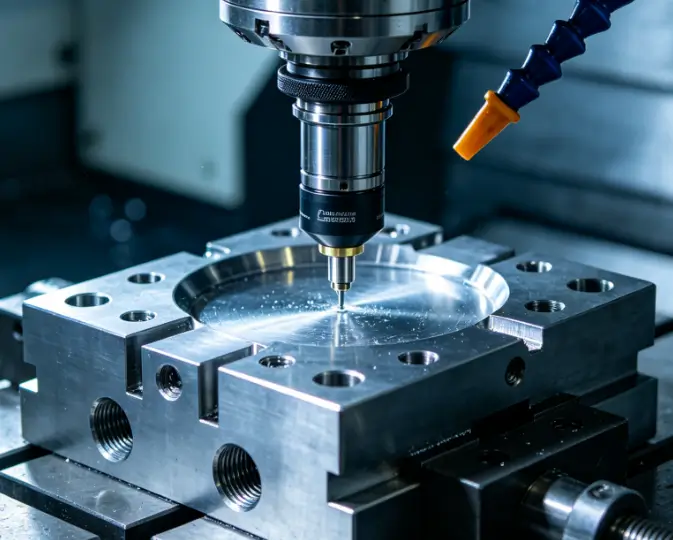
Tool setters (mechanical or laser) are essential tools for improving tool setting accuracy and efficiency, especially in mass production. Unlike the trial cutting method, tool setters use high-precision sensors to quickly measure the relative position between the tool and the workpiece, converting electrical signals into coordinate data for automatic setting—achieving an accuracy of up to 0.001mm. Here’s a step-by-step guide for beginners (applicable to most mainstream CNC systems like FANUC, Siemens, and Mitsubishi):
1. Preparatory Work
- Check the CNC milling machine: Ensure the spindle, guide rails, and lubrication system are operating normally, and perform a machine zero return (homing) to reset the machine coordinate system datum.
- Install the workpiece and tool: Secure the workpiece firmly with a fixture to avoid displacement during machining; install the required tool and ensure it is tightly clamped.
- Calibrate the tool setter: Clean the tool setter probe (ruby contact for mechanical types) and verify its accuracy to ensure reliable measurement data.
2. Mechanical Tool Setter Operation Steps
- Install the tool setter on the machine table and position it in a safe area (avoiding tool movement paths).
- Spindle positioning: Set the spindle speed to below 200rpm to ensure safe contact between the tool and the tool setter probe.
- Tool contact measurement: Manually operate the handwheel to move the tool slowly, making it contact the tool setter probe. The tool setter will send a signal to the CNC system when contact is made.
- Record data: The system automatically records the tool length and radius compensation parameters, which can be directly used for subsequent machining.
3. Laser Tool Setter Tips (Advanced)
Laser tool setters use non-contact light curtain detection to measure tool contours, making them ideal for small tools. Note to eliminate ambient light interference during use, and calibrate the laser sensor regularly to maintain measurement accuracy.
Work Coordinate System & G54 G55: The Core of CNC Machining
The work coordinate system (also called the programming coordinate system) is a user-defined coordinate system established based on the workpiece design datum. Its origin (workpiece zero point) is usually selected at the workpiece’s symmetry center, end face, or datum edge, and it is called by G-code commands (G54-G59) to achieve flexible machining. For beginners, G54 and G55 are the most commonly used—here’s what you need to master:
What Are G54 and G55?
G54 and G55 are modal commands (once executed, they remain in effect until replaced by another coordinate system command) that call preset work coordinate systems. They store the offset values between the workpiece zero point and the machine zero point (machine coordinate system origin, a fixed datum set by the manufacturer that cannot be changed).
- G54: The default work coordinate system, used for the main workpiece or the first machining process.
- G55: The second preset work coordinate system, used for multi-workpiece machining or multi-process machining on the same workpiece.
Work Coordinate Offset Setting (Practical Operation)
Work coordinate offset is the key to aligning the work coordinate system with the machine coordinate system. Here’s how to set it using the tool setter (taking FANUC system as an example):
- After completing tool setting, move the tool to the workpiece zero point (e.g., the top surface center of the workpiece).
- Press the "OFSSET" button on the control panel to enter the G54-G59 coordinate system interface.
- Position the cursor on the X, Y, or Z axis of G54 (or G55), input the offset value (the machine coordinate value of the workpiece zero point), and click the "Measure" soft key to save.
- Verify: Switch to MDI mode, input "G54 G90 G00 X0 Y0 Z100" (G90 for absolute coordinate mode, Z100 for safe height), start the program at 0% feed rate, and gradually increase the rate to confirm no collision occurs.
Multi-Work Coordinate System Management (Boost Efficiency)
In batch production or multi-process machining, managing multiple work coordinate systems (G54-G59) can significantly improve efficiency—no need to re-set the coordinate system for each workpiece or process. Here are practical tips for operators and training students:
1. Reasonable Assignment of G54-G59
Assign coordinate systems based on machining needs: Use G54 for the first workpiece, G55 for the second, and so on. For multi-process machining, assign different coordinate systems to different process datums to avoid confusion.
2. Quick Switching Between Coordinate Systems
Simply add the corresponding G-code (G54/G55) at the beginning of the machining program to switch between coordinate systems. For example:
| gcodeG54 G0 X10 Y10 ; Use G54 coordinate system to move to (10,10)G55 G0 X5 Y5 ; Switch to G55 coordinate system and move to its (5,5)G0 X0 Y0 ; Still use G55 coordinate system to move to its origin |
3. Parameter Backup and Calibration
Regularly back up the offset values of G54-G59 (stored in the system’s EEPROM) to avoid data loss due to power failure. After replacing the fixture or workpiece, re-calibrate the coordinate offset to ensure accuracy.
On-Machine Measurement Tool Setting (Advanced Skill)
On-machine measurement tool setting combines tool setting and workpiece measurement, allowing real-time adjustment of tool parameters and coordinate offsets during machining-reducing offline measurement time and improving machining accuracy. It is especially suitable for complex workpieces and large-batch production.
Key Operation Steps
- Install the on-machine measurement probe on the spindle (replace the cutting tool).
- Call the measurement program: The probe moves to the workpiece surface to measure key dimensions (e.g., length, width, hole position).
- System adjustment: The CNC system automatically calculates the deviation between the actual measurement value and the theoretical value, and adjusts the tool length compensation or work coordinate offset accordingly.
- Verify: Perform a small amount of trial cutting on the scrap area of the workpiece to confirm the adjustment effect.
Tips for Beginners
When using on-machine measurement, ensure the probe is clean and free of debris; avoid collision between the probe and the workpiece or fixture. For operators just starting out, practice with simple workpieces first to familiarize yourself with the measurement program and parameter adjustment logic.
Common Tool Setting & Coordinate System Mistakes (Avoid These!)
Even experienced operators can make mistakes—here are the most common issues and solutions to help you avoid scrap parts and equipment damage:
1. Tool-Workpiece Collision
Cause: Failure to perform machine zero return before tool setting, delayed tool retraction, or starting the program at high feed rate.
Solution: Press the emergency stop button immediately; re-perform machine zero return; start the program at 0% feed rate and gradually increase.
2. Large Machining Dimensional Deviation
Cause: Forgetting to include tool diameter/length in offset calculations, failing to zero the relative coordinate, or loose workpiece clamping.
Solution: Recheck offset calculations, re-perform tool setting, and re-clamp the workpiece.
3. Invalid Coordinate Value Input
Cause: Selecting the wrong coordinate system (e.g., G55 instead of G54), failing to click "Measure" after inputting values, or machine lock status.
Solution: Confirm the target coordinate system, click "Measure" to save values, and unlock the machine.
4. Z-Axis Overcut/Undercut
Cause: Excessive cutting depth, incomplete tool-workpiece contact, or tool wear.
Solution: Adjust cutting depth to 0.1-0.2mm, re-perform Z-axis tool setting, and replace worn tools or adjust tool length compensation.
Final Tips for Mastering CNC Milling Tool Setting & Work Coordinate System
For operators and training students, mastering tool setting and work coordinate system setup takes practice—but following these principles will speed up your progress:
- Start with the basics: Master the trial cutting method first, then move on to tool setter and on-machine measurement.
- Memorize G54/G55 usage: These are the most commonly used commands—practice switching and setting offsets until it becomes second nature.
- Prioritize safety: Always perform machine zero return, check tool and workpiece clamping, and use low feed rates when verifying.
- Record and summarize: Keep a log of tool setting parameters and common mistakes to avoid repeating them.
By mastering tool setter usage, work coordinate offset, multi-work coordinate management, and on-machine measurement, you’ll become a proficient CNC milling operator—reducing scrap rates, improving efficiency, and ensuring precise machining every time. Whether you’re a beginner or looking to upgrade your skills, this guide is your go-to resource for mastering CNC milling machine tool setting and work coordinate system setup.
 Email
Email sales1: +86 15312799623