



CNC Slant-Bed Lathe: Linear Guides vs Box Ways
Ball linear guides suit short-cycle parts with frequent rapid moves and light-to-medium cutting loads. Preloaded roller linear guides balance speed and load capacity and are often the strongest all-round option for medium-diameter production turning. Box ways deserve priority when sustained heavy cutting, interrupted cuts, impact resistance, and vibration damping dominate. Guideway type alone does not prove machine accuracy; the purchase decision must also consider the spindle torque curve, turret rigidity, thermal behavior, chip and coolant systems, and ISO positioning test results.
Why Guideway Type Alone Does Not Predict CNC Lathe Performance
The common procurement mistake is not a lack of specifications; it is treating one structural label as a proxy for total machine performance. All three guideway types can be used on slant-bed lathes, but they make different tradeoffs in friction, damping, stiffness, acceleration, and maintenance. Convert the following risks into acceptance criteria during the RFQ stage.
· Catalog rapid traverse overstates cycle-time benefit: m/min is a speed ceiling, while short moves are often limited by acceleration, jerk, and in-position settling time.
· Guideway type is used as a substitute for heavy-cutting evidence: continuous spindle torque, turret interface, workholding, bearing temperature, and chip evacuation may be the real limits.
· Accuracy promises omit operating condition: cold positioning accuracy, thermally stabilized dimensional consistency, and loaded cutting accuracy are different measurements.
These errors create two direct costs. A buyer may pay a capital and maintenance premium for a heavy structure the process never uses, or the selected machine may develop chatter, size drift, and tool-life variation under the target material and cutter load, erasing its nominal cycle-time advantage through tuning and rework.
Ball vs Roller Linear Guides vs Box Ways: Key Differences
| Criterion | Ball linear guide | Roller linear guide | Box way |
| Contact and motion | Recirculating rolling balls | Recirculating rollers; usually a larger effective contact area | Sliding surface, often with a low-friction liner |
| Primary advantage | Low friction, fast response, and high acceleration potential | Higher load capacity and stiffness than a comparable ball design while retaining rolling efficiency | Large bearing area; structural damping and shock resistance are generally favorable |
| Primary limitation | Heavy-load and impact performance depend strongly on size, span, block count, and preload | Usually higher component cost and tighter installation requirements than ball guides | Friction and lubrication sensitive; stick-slip control, fitting, and maintenance demand more attention |
| Best-fit work | Small diameters, frequent indexing, short cycles, light-to-medium cuts | Mixed roughing and finishing, medium batches, speed and load both important | Difficult materials, interrupted cuts, deep cuts, and vibration-sensitive work |
| Verify in the RFQ | Preload class, block count, axis acceleration, lubrication interval | Roller model, rated load, preload, and installation span | Liner material, lubrication, scraping or fitting method, and thermal compensation |
Boundary condition: this table describes structural tendencies, not a machine ranking. Roller guides can support heavy cutting, and box-way machines can achieve high rapid rates. Final capability depends on complete machine design and manufacturing quality.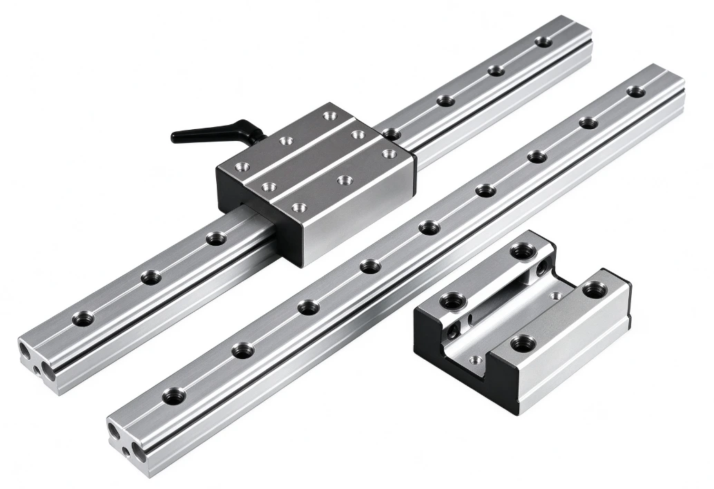
How Guideway Stiffness Affects CNC Lathe Performance
Static guideway stiffness at a specified load point can be expressed as the applied load divided by the corresponding deflection:
K = P / δ
K may be reported in N/μm, P is the load in a defined direction, and δ is the resulting displacement. K is a secant stiffness for a particular structure, direction, and load range; it is not a universal constant. THK states that preload reduces displacement, and its illustrated case shows approximately half the displacement of an unpreloaded guide. That ratio must not be transferred to another guide size or a complete machine without verification.
A reproducible stiffness requirement must define load direction, load point, block count, rail spacing, preload class, measurement location, and load range. A bare N/μm number without those conditions is not auditable.
CNC Slant-Bed Lathe Specifications: Four Published Examples
The machines below show what different guideway architectures can deliver in published configurations. This is not a same-price, same-control, or same-option ranking. Confirm every ordered machine against the manufacturer’s signed quotation and technical agreement.
| Machine and guideway | Max turning dia. mm | Max turning length mm | Spindle rpm | Power kW max./cont. | Torque N·m max./cont. | X/Z rapid m/min | Tools |
| Hyundai WIA E200ALM guide | 350 | 300 | 6000 | 15/11 | 95.5/52.5 | 36/36 | 12 |
| Hyundai WIA E200PABox guide | 350 | 280 | 6000 | 15/11 | 95.5/52.5 | 24/24 | 12 |
| Hyundai WIA SE2200ARoller LM guide | 350 | 340 | 6000 | 15/11 | 127/70 | 30/36 | 12 |
| Hwacheon Hi-TECH 200ABox ways | 350 | 401 | 5000 | 15/11 | 114.5/84.3 | 30/30 | 12 |
Data scope: Hyundai WIA’s E200 source lists 95.5/52.5 N·m; the frequently repeated 95.6 N·m value reflects rounding or a document-version difference. Hi-TECH 200A variants also include a 3500 rpm, 163.6/120.1 N·m configuration; this table uses the 5000 rpm version. SE2200A is the 6-inch-chuck version. Region, control, and option packages may change delivered specifications.
What the table cannot prove: the cited catalogs do not publish positioning accuracy, repeatability, axis acceleration, thermal drift, cutting stiffness, and coolant flow under one common test condition. The table therefore cannot establish which machine is most accurate or fastest in a real cycle.
How Rapid Traverse Speed Affects CNC Lathe Cycle Time
If an axis has already reached constant speed and acceleration is ignored, travel time can be approximated by:
t = L / v
For 6 m of accumulated non-cutting travel, 24 m/min gives 15 s and 36 m/min gives 10 s, a theoretical 5 s difference. At only 0.5 m, the constant-speed difference is about 0.42 s. These are speed-ceiling comparisons, not cycle guarantees.
For symmetric acceleration and deceleration while ignoring jerk, use a piecewise model:
If L ≥ v²/a: t = L/v + v/a
If L < v²/a: t = 2√(L/a)
Here a is axis acceleration. The second case describes a short move that never reaches rated rapid speed, so raising the catalog m/min value may deliver almost no benefit. A complete cycle also includes jerk limits, turret indexing, spindle acceleration, chuck motion, probing, and in-position settling. For acceptance, run the agreed program for at least 30 stable cycles and report the mean, standard deviation, and abnormal stops.
Which Guideway Fits Your Workpiece and Cutting Process?
| Operating condition | Priority candidate | Procurement evidence | Required trial or test |
| Aluminum, brass, small steel parts; short cycles and frequent indexing | Ball linear guide | Axis acceleration, turret index, spindle response, automation cycle | Complete automatic cycle and sustained-run stability |
| Carbon or stainless steel; rough and finish on one machine | Roller linear guide | Continuous torque, roller preload, turret interface, thermal compensation | Finish size and surface quality after loaded roughing |
| Superalloy, hardened stock, forgings, or interrupted cuts | Box way or a proven heavy-duty roller design | Low-speed continuous torque, machine mass, workholding, lubrication, chip evacuation | Vibration, power, and tool life at the planned maximum depth of cut |
| Thin-wall rings, long shafts, or deformation-sensitive parts | Do not decide by guideway alone | Fixture distortion, tailstock or steady rest, heat input, metrology plan | Size and roundness after unclamping |
| High-mix, low-volume production | Decide by changeover and support | Tool setting, program compatibility, fixture changes, spare-parts lead time | Total changeover time across three representative parts |
How to Build a CNC Lathe Tolerance Budget
Part tolerance is not synonymous with machine positioning accuracy. Fixture error, tool behavior, thermal state, measurement, and material relaxation also contribute. Procurement teams may use the following two models, but their meanings must remain separate.
Worst-Case Tolerance Stack-Up
T_allow ≥ |E_bias| + Σ Tᵢ
This conservative model limits all contributors as if they act in the least favorable direction. E_bias is uncorrected systematic error and Tᵢ is the allowed band for each contributor. If a 20 μm total tolerance assigns 25% to machine positioning and thermal drift, that allocation is 5 μm. The arithmetic is correct, but it is only a design allocation; it does not prove that the machine can produce a 20 μm part tolerance.
RSS Combination of Independent Random Uncertainties
u_c = √Σ(cᵢuᵢ)²
U = k·u_c
u_c is combined standard uncertainty, cᵢ is a sensitivity coefficient, and U is expanded uncertainty. Measurement uncertainty primarily informs conformity decisions and guard bands; it should not be added linearly to process error without analysis. Known systematic errors should be corrected or bounded separately.
Contract recommendation: define the standard edition, target positions, repetitions, approach directions, warm-up cycle, environmental temperature and rate of change, traceable measuring equipment, compensation state, data-reduction method, and rejection rule. ISO 13041-4:2004 remains current, but its tolerance framework normatively references ISO 230-2:1997. If the parties want to use ISO 230-2:2014 and its 2016 amendment for measurement and evaluation, they should state the scope and order of precedence in writing.
What Acceptance-Test Evidence Should a Lathe Supplier Provide?
This article does not treat unavailable factory video or dashboard screenshots as evidence, and it contains no unresolved media placeholders. A published page may add genuine site media, but the media should be accompanied by a citable text record so the evidence remains understandable without playing a video.
1. Laser interferometer record: machine ID, X or Z axis, measured length, target count, bidirectional runs, ambient temperature, compensation state, positioning deviation, repeatability, and calibration certificate number.
2. Thermal drift record: measure the same feature at fixed intervals after cold start for at least the planned shift length, and publish the dimensional trend rather than a single final conforming part.
3. Loaded cutting record: material grade, stock condition, tool, depth of cut ap, feed f, cutting speed vc, spindle load, vibration or roughness Ra, and parts produced before the tool reaches its rejection criterion.
4. Coolant and chip record: report pressure and flow together. Flow may be stated in L/min or m³/h; 1 m³/h = 16.667 L/min. MPa alone does not prove sufficient heat and chip removal.
CNC Lathe Cycle-Time Case Study: What the Data Proves
A Hwacheon case study describes a two-piece aluminum housing assembly for the Boeing 787. Main-piece cycle time fell from 64 to 28 min, cover cycle time from 45 to 20 min, and stated lead time for a 650-part lot from 10 to 4 weeks. The source also states that the machine typically runs two shifts. The case demonstrates a substantial result for one part, workholding method, tool package, and redesigned process; it does not prove that every box-way lathe will produce the same improvement.
The main-piece cycle reduction is (64−28)/64 = 56.25%; the cover reduction is (45−20)/45 = 55.56%; and the lead-time reduction is (10−4)/10 = 60%. Once quantities are defined, theoretical machine-hours saved are:
H = (36N_main + 25N_cover) / 60
| Quantity interpretation | Substitution | Theoretical hours saved |
| All 650 parts are main pieces | N_main=650, N_cover=0 | 390.0 h |
| All 650 parts are covers | N_main=0, N_cover=650 | 270.8 h |
| 650 total parts, 325 of each | N_main=325, N_cover=325 | 330.4 h |
| 650 assemblies, one of each | N_main=650, N_cover=650 | 660.8 h |
The source says “650-part lot size” but does not establish whether that means 650 total components or 650 assemblies. The four values above are conditional calculations, not reported actual machine-hour savings.
Five Steps to Select a CNC Slant-Bed Lathe
1. Define the part family: materials, maximum diameter and length, stock condition, annual volume, roughing allowance, and critical tolerances.
2. Define the load: target depth of cut ap, feed per revolution f, tool overhang, interrupted-cut ratio, and low-speed continuous torque.
3. Evaluate cycle time with the actual program: include tool changes, spindle response, chucking, probing, automation, and settling time.
4. Lock down thermal and acceptance conditions: separate cold, warm, unloaded positioning, and loaded cutting results.
5. Compare lifecycle cost: lubrication, scraping or block replacement, spare-parts lead time, service response, energy, tool life, and downtime.
Practical decision: validate ball linear guides first for frequent rapid moves and light-to-medium cuts; validate roller linear guides first when speed and load capacity must be balanced; validate box ways first for sustained heavy or interrupted cutting where damping is critical. Any of the three can be the right choice when supported by test data from the intended duty cycle.
CNC Lathe Guideway FAQ
Q: Ball vs roller linear guides: which is better for heavy CNC turning?
A: At a comparable size, roller contact commonly supports higher load and stiffness, but machine-level performance also depends on rail spacing, preload, bed structure, ball screws, bearings, turret, and continuous spindle torque. Compare rated load and stiffness, then trial-cut at the planned maximum parameters.
Q: Do box ways make a CNC lathe more accurate than linear guides?
A: No. Box ways generally emphasize damping and shock resistance, while rolling guides offer low friction and fast response. Geometry, thermal compensation, assembly quality, and feedback architecture also control accuracy. Use results from an agreed test standard rather than inferring accuracy from the guideway name.
Q: How much cycle time does 36 m/min rapid traverse save over 24 m/min?
A: A short move may begin decelerating before it reaches rated speed, making acceleration and jerk the dominant variables. The total cycle also includes indexing, spindle response, clamping, and measurement. Time the actual program over stable repeated cycles.
Q: What positioning accuracy does a CNC lathe need for a 20 μm part tolerance?
A: There is no universal ratio. Separate systematic bias, random process variation, fixture, tool, thermal drift, and measurement uncertainty, then allocate a machine budget using process capability and risk. A 5 μm allocation may be a design example, but it still requires validation on the target part and measurement system.
 Email
Email sales1: +86 15312799623