Double-spindle lathe linkage processing technique: Alignment processing method for symmetrical parts without tool marks
In the process of the manufacturing industry's development towards high efficiency and precision, the double-spindle lathe linkage processing technology is becoming the key to breaking through the bottleneck of symmetrical parts processing. This article focuses on the linkage processing of double-spindle lathes, deeply analyzing the alignment processing method for symmetrical parts without tool marks. From the core principle to practical operation skills, it comprehensively presents how this technology helps achieve dual improvements in efficiency and accuracy in the processing of long shaft parts.
The core of the double-spindle lathe linkage processing technique lies in enabling the two spindles to work synchronously and collaboratively by means of the alignment processing method. Through precise synchronous control parameter Settings, the tools driven by the left and right spindles can simultaneously process symmetrical parts. With a single clamping, the processing operations at both ends of the part can be completed. This fundamentally avoids the problem of tool marks caused by secondary clamping in traditional single-spindle processing, ensuring that there are no tool marks on the surface of symmetrical parts and meeting the requirements of high-precision processing.
So, how exactly does this top-alignment processing method function in actual processing? What key parameters are involved in the synchronous control of dual spindles? The subsequent content will reveal it to you one by one, guiding you to fully grasp the secrets of the double-spindle lathe's linked processing and helping enterprises achieve new breakthroughs in the field of long shaft parts processing.
I. Why has dual-spindle linkage machining become the new favorite in manufacturing?
When processing symmetrical parts with a traditional single spindle, engineers often fall into three predicaments, and the dual-spindle technology is precisely the targeted solution.
The three major pain points of traditional single-spindle machining
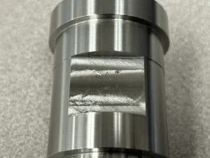
The problem of tool marks: When processing symmetrical parts, two clamps are required. At the joint, step-like tool marks of 0.01-0.03mm are prone to occur, causing the surface roughness to deteriorate from Ra0.8 to above Ra1.6. For critical parts such as seals and bearing mating surfaces, it may directly lead to the scrapping of the parts.
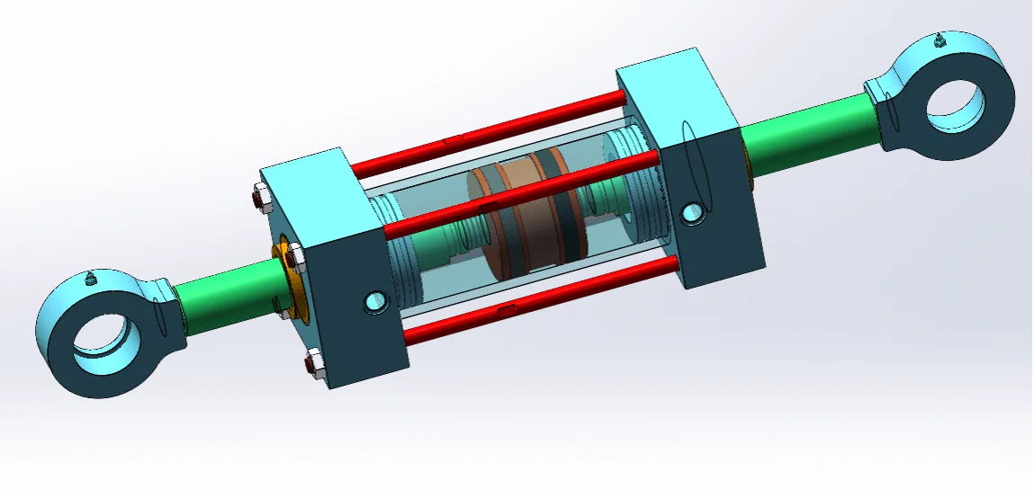
Secondary clamping error: When turning over for processing, re-aligning and positioning will result in a coaxiality error of 0.02 to 0.05mm. When a certain hydraulic components factory was manufacturing φ50mm piston rods, due to secondary clamping, the diameter deviation at both ends reached 0.03mm, which failed to meet the assembly requirements, and the rework rate was as high as 15%.
The efficiency bottleneck of long shaft processing: For parts with a length-to-diameter ratio (L/D) greater than 10 (such as a 1-meter-long drive shaft), single-spindle processing requires multiple tool passes. Moreover, due to the vibration that is prone to occur during cantilever processing, the processing time for a single piece often exceeds 15 minutes, and the daily production capacity is difficult to exceed 30 pieces.
The advantages of dual-spindle linkage machining
The double-spindle lathe fundamentally resolves the pain points of traditional processing through the coordinated operation of the left and right spindles:
One-time clamping eliminates tool connection marks: Both ends of the part are processed simultaneously without turning around, avoiding the tool connection problems brought about by secondary clamping. After application in a certain automotive bearing factory, the defect rate of joint tool marks dropped from 22% to 0%, and the surface roughness stabilized at Ra0.4-0.8μm.
Efficiency increase of 50%-100% : Symmetrical features are processed simultaneously, eliminating the need for repeated positioning time. A certain construction machinery factory processes a drive shaft with a diameter of 80mm×500mm. The processing time for a single piece has been shortened from 12 minutes to 5 minutes, and the daily production capacity has been increased from 60 pieces to 140 pieces.
Top support solves vibration problems: Double spindles hold the long shaft at the top, transforming the cantilever beam structure into a simply supported beam structure, and increasing rigidity by 3 to 5 times. When L/D=15, the vibration amplitude drops from 0.02mm to 0.003mm, and high-speed cutting can be stably achieved.
Analysis of Technical Highlights of Popular Dual-Spindle Models at the Exhibition
There are currently two mainstream dual-axis layouts, suitable for different scenarios:
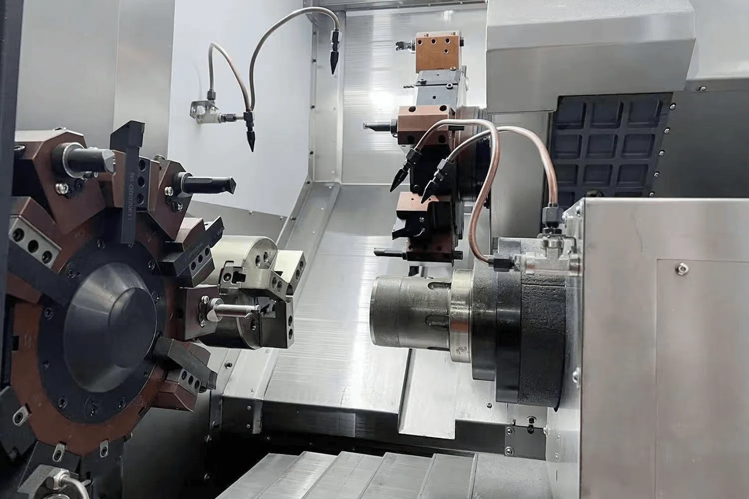
Left and right parallel layout: The main shaft axes are on the same horizontal plane, and the spacing is adjustable (usually 50-300mm). It is suitable for processing long shaft parts with a length of 300-1000mm, such as automotive drive shafts and hydraulic piston rods. Representative models include DMG MORI CTX beta 800 TC and Shenyang Machine Tool HTC4020 double-spindle lathe.
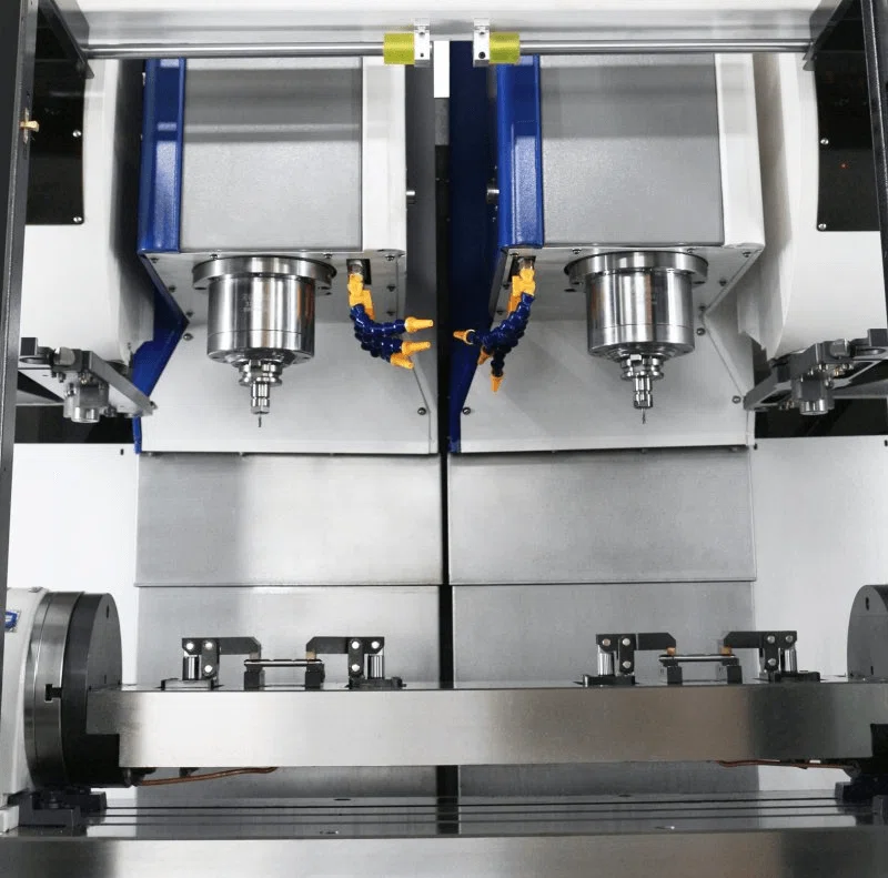
Vertical layout up and down: The main shaft is distributed from top to bottom, saving 30% of the floor space. It is suitable for small and medium-sized symmetrical parts with diameters ranging from 50 to 200mm, such as gear shafts and connectors. Typical models include Haas ST-20Y and Doosan PUMA TT1800.
The synchronous control technology of the latest model has been realized:
The speed synchronization response time is ≤0.1 seconds (0.5 seconds for traditional models).
The position synchronization accuracy is ≤0.001mm
Supports real-time dynamic error compensation (automatically corrected within ±0.002mm)
II . Core Principle of the top alignment machining Method: From mechanical structure to control system
The key to achieving no tool marks on the double-spindle alignment lies in the rigid design of the mechanical structure and the precise synchronization of the control system.
Mechanical stability design for top machining
The concentricity requirement for the double spindles: The coaxiality of the left and right spindles must be controlled within ≤0.005mm; otherwise, radial force will be generated during processing, causing the part to bend or resulting in tool marks. Debugging method: Use a standard inspection rod (accuracy 0.001mm) to hold both ends of the left and right main shafts respectively. Use a dial indicator to detect the runout in the middle section and adjust it to the qualified range through the main shaft fine-tuning knob.
Rigid support scheme
The main shaft bearings adopt high-precision angular contact ball bearings(such as NSK 7000 series), with radial runout ≤0.002mm
The tailstock is hydraulically driven, and the clamping force is adjustable (3-5kN for steel parts and 1-2kN for aluminum parts)
A tool rest can be added to the middle part of the long shaft (it is recommended to use a 3-claw type, with the hardness of the support surface ≥HRC55).
The three key parameters for spindle synchronous control
Speed synchronization error setting: The speed difference between the left and right spindles should be ≤1rpm. Parameter setting example
FANUC system: Parameter No.3745 (spindle synchronization allowable error) is set to 1
Siemens system: MD35030 (SYNC_ERROR_LIMIT) is set to 1rpm
Torque matching parameters: Allocate the left and right spindle torques based on the material hardness to prevent parts from slipping or deforming due to uneven force distribution.
Steel parts (such as 45# steel) : The ratio of left to right torque is 1:1
Aluminum alloy: The torque of the left spindle can be reduced by 20% (to avoid over-pinching damage)
Titanium alloy: The torque of the right spindle increases by 10% (enhancing driving force)
Feed speed coordination: Use synchronous G code to ensure consistent feed for the left and right tools
G100: Rigid synchronous mode (suitable for high-precision processing, feed error ≤0.001mm)
G101: Flexible Synchronous Mode (Suitable for long shaft processing, allowing dynamic compensation of ±0.003mm)
Programming example
plaintext
G100 P1 (Start spindle 1 and Spindle 2 rigidly synchronous)
S1200 M03 (Dual spindle synchronous start, speed 1200rpm)
G01 X50 Z-100 F0.2 (Synchronous feed of left and right tools)
The support of the numerical control system for linked processing
All mainstream numerical control systems offer dual-spindle synchronization functionality. Comparison of key parameter Settings:
System model | Synchronous control parameters | Set value | Function Description |
FANUC 31i | 3740 (Synchronous shaft selection) | 1 | Define the main shaft 2 as the synchronous following shaft |
FANUC 31i | 3744 (Synchronous Gain) | 8000 | Synchronous response speed (the higher the value, the faster the response) |
Siemens 828D | MD35000 (SYNC_MODE) | 1 | Enable the location synchronization mode |
Siemens 828D | MD35050 (SYNC_GAIN) | 500 | Synchronous control gain |
The method for enabling the synchronous error compensation function
Enable "Dynamic Error Compensation" in the system parameters (FANUC parameter 3750=1, Siemens MD35100=1)
Perform synchronous calibration: After processing the standard specimen, measure the dimensional deviation at both ends and input the compensation value (usually within 0.001-0.003mm)
Set the effective conditions for compensation (such as automatic compensation when the error of three consecutive parts exceeds 0.002mm)
III .6-step Practical Skills for Processing without Tool Marks
Master the following practical steps, and even if you are using a double-spindle lathe for the first time, you can achieve seamless tool mark processing.
1. Selection of workpiece clamping and positioning references
Double ejector pin + chuck combination solution
Short parts (L<300mm) : The left spindle is clamped with a three-jaw chuck (clamping length ≥ 1.5 times the diameter), and the right spindle is tightened with a free center pin
Long parts (L>500mm) : Both the left and right spindles use dead center pins, which are used in conjunction with the tool rest (a support point is set every 300mm).
Thin-walled parts: Elastic clamps are adopted, reducing the clamping force by 30% and preventing deformation
Positioning reference accuracy requirements:
Center holes at both ends: roundness ≤0.005mm, consistent depth (error ≤0.1mm)
Clamping end face: Flatness ≤0.01mm, perpendicularity to the center hole ≤0.005mm
2. Principles of tool path planning
Symmetrical tool mirror programming
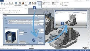
In CAM software (such as Mastercam, UG), simply draw the tool path on one side and generate the path on the other side through the "Mirror function". Key Settings
Select "Main Axis centerline" for the mirror axis
Enable the "Tool Radius Compensation Synchronization" function
Set the tool interference check distance (≥0.5mm)
Safe distance setting
The left and right tools should maintain a safety distance of 0.5 to 1mm at the closest positions. During programming, the G49 command can be used to temporarily cancel tool compensation to avoid collisions. Example
plaintext
G00 X20 Z5 (Move the left knife quickly to a safe position)
G49 (Tool compensation cancelled)
G00 X20 Z-50 (Move the right tool to the processing position and keep a safe distance from the left tool)
G41 (Reactivation Compensation)
3. Synchronous start and stop control
Spindle synchronous start: Precise synchronization is achieved by using M code in combination with S instructions
plaintext
M199 P1 S1000 (Spindle 1 and spindle 2 are ready to start synchronously, target speed 1000 RPM)
M03 (Dual-spindle Synchronous Start)
Note: Before starting, it is necessary to confirm that the spindle rotation directions are consistent (both are M03 or M04)
Emergency stop handling
When the emergency stop button is pressed in case of an emergency, the system will automatically execute:
Simultaneous deceleration of both spindles (deceleration of 100rpm/ms)
The tool quickly retreats to a safe position (G28 return reference point)
Record the current processing position. After restarting, you can resume from the breakpoint
4. Symmetrical matching of cutting parameters
The cutting parameters of the left and right spindles need to be kept balanced to avoid synchronization errors caused by uneven load.
Parameter balance formula
Feed rate of the right spindle = feed rate of the left spindle × (Speed of the right spindle/speed of the left spindle)
For example, for the left spindle, v_c=100m/min (S=637rpm), f=0.15mm/rev
Right spindle: v_c=100m/min (S=637rpm), f=0.15mm/rev (fully synchronous)
Material compatibility Parameter table
Material | Cutting speed v_c (m/min) | Feed rate f (mm/rev) | Cutting depth a_p (mm) |
45# steel | 100-120. | 0.1-0.2 | 1 to 2 |
Aluminum alloy | 300-400. | 0.15-0.3 | 1.5 3 |
Titanium alloy | 60-80. | 0.05-0.1 | 0.5 1 |
5. Real-time error monitoring and adjustment
Synchronous error alarm threshold: Set at 0.002mm. When the system detects that the position deviation of the left and right spindles exceeds this value, it will automatically pause and alarm. Parameter Settings
FANUC: No.3746=2 (unit: 0.001mm
Siemens: MD35040=2
Online measurement system integration
Install contact probes (such as Renishaw OMP40-2) on the tool turret and automatically measure every 5 parts processed:
Measure the difference in diameter between the two ends (it should be ≤0.003mm)
Check the roundness of the middle part (it should be ≤0.002mm)
The system automatically adjusts the synchronous compensation value based on the measurement results
6. Typical defect solutions
Five Causes of knife marks and Their solutions:
If the concentricity of the main shaft exceeds the tolerance, recalibrate the main shaft to ensure it is ≤0.005mm
Excessive synchronization error → Reduce the feed rate by 10% and increase the synchronization gain
Inconsistent tool wear → Replace both left and right tools simultaneously to ensure consistent cutting edge conditions
Cutting parameters do not match → Adjust the feed rate according to the balance formula
Loose workpiece clamping → Increase the clamping force (for steel parts, it can be increased to 6kN)
Vibration causes accuracy to exceed tolerance:
Check the support strength of the tool rest and adjust it until there is no radial shaking of the workpiece
Reduce the cutting speed by 20% or increase the cutting depth (to avoid vibration caused by thin cutting)
Replace the cutting tools with better rigidity (such as using solid carbide tool holders)
IV .Case of Doubling the Processing Efficiency of Long Shaft Parts
An example of automotive drive shaft processing
A certain auto parts factory processes 45# steel drive shafts (φ60mm×800mm). The traditional single-spindle processing flow is:
Left end rough turning (3 minutes) → Fine turning (2 minutes)
Turn around and clamp (5 minutes) → Rough turning at the right end (3 minutes) → fine turning (2 minutes)
Total processing time: 15 minutes, daily production capacity (8 hours) : 32 pieces
After adopting double-spindle alignment processing:
Simultaneous rough turning of the left and right spindles (3 minutes) → simultaneous finish turning (2 minutes)
No need to turn around, and the clamping time is shortened to 1 minute
Single-piece processing time: 6 minutes, daily production capacity: 80 pieces (an increase of 150%
Key parameter Settings
Spindle speed: 800rpm (synchronization error ≤1rpm)
Feed rate: 0.15mm/rev (fully synchronized on both sides)
Synchronization mode: G100 rigid synchronization
Result: The diameter tolerance was controlled within ±0.005mm, with no tool marks and a surface roughness of Ra0.8μm
Processing improvement of hydraulic piston rods
A certain hydraulic components factory produces 20CrMnTi piston rods (φ50mm×600mm). The original process has two major problems:
The poor sealing caused by the knife marks leads to a leakage rate of 8%
The daily production capacity is only 50 pieces, which cannot meet the order requirements
After applying the double-spindle alignment processing:
The leakage rate was reduced to 0% by eliminating the tool marks through a single clamping
Optimization parameters: v_c=110m/min, f=0.12mm/rev, and the G101 flexible synchronization mode is adopted
The surface roughness was increased from Ra1.6μm to Ra0.8μm
The processing time for a single piece has been shortened from 10 minutes to 4 minutes, and the daily production capacity has been increased to 120 pieces
Processing of long shaft parts for medical devices
A certain medical device enterprise processes titanium alloy bone nail guide rods (φ10mm×400mm), with the following requirements:
No knife marks (to avoid scratching the tissue)
Accuracy ≤0.003mm
Aseptic processing environment
Dual-spindle processing solution
Adopt a double-spindle lathe with an upper and lower layout (to avoid chip accumulation)
Use food-grade coolant (compliant with FDA standards)
Spindle synchronization parameters: Rotational speed 500rpm, torque ratio 1.1:1 (slightly higher for the right spindle)
Calibrate the concentricity of the main shaft before daily processing (ensure ≤0.002mm)
Effect
The processing accuracy is stable within 0.002mm
The surface roughness is Ra0.4μm, and there are no tool marks
The efficiency is 80% higher than that of a single spindle, meeting the production requirements of implantable devices
V .Selection and Investment Return Analysis of Double-Spindle Lathes
A guide to selecting models with different budgets
Entry-level (100,000-200,000 yuan)
Configuration: Economical numerical control system (such as Guangshu 988TDb), spindle speed 3000rpm, synchronization accuracy 0.005mm
Applicable scenarios: Medium and small batch production (daily production capacity ≤50 pieces), general parts with low precision requirements (±0.01mm)
Limitations: No dynamic error compensation, and the vibration during long shaft processing is relatively obvious
Professional grade (200,000-500,000 yuan)
Configuration: FANUC 0i-TF or Siemens 828D system, spindle speed 4000-6000rpm, synchronization accuracy 0.002mm, with dynamic compensation
Applicable scenarios: Large-scale production (daily production capacity of 50-200 pieces), automotive/hydraulic parts with precision requirements of ±0.005mm
Cost-performance highlights: The payback period is usually 8 to 12 months
High-end customization (over 500,000 yuan)
Configuration: FANUC 31i or Siemens 840D system, spindle speed above 8000rpm, synchronization accuracy 0.001mm, with online measurement
Applicable scenarios: High-precision fields such as aerospace and medical devices (accuracy ≤0.003mm)
Customization options: It can be integrated with automatic loading and unloading and error-proof detection systems
Calculation of the investment return period
Take the professional-grade double-spindle lathe (350,000 yuan) as an example
Labor cost savings
Traditional single spindle: Two people operate one machine (one for clamping and the other for monitoring), with a combined monthly salary of 15,000 yuan
Double-spindle lathe: One person can operate two machines, and the labor cost has been reduced to 3,750 yuan per machine per month
Annual savings: (15,000 -0.375)×12 = 135,000 yuan
Material cost savings
The scrap rate of traditional processing is 8%, while that of dual-spindle processing is 1%
Based on an average daily processing of 100 pieces and a material cost of 50 yuan per piece:
Annual savings: 100×300×50×(8%-1%) = 105,000 yuan
Capacity increase benefits
The efficiency has been increased by 100%, with an additional annual output value of approximately 200,000 yuan
Total annual income: 135,000 + 105,000 + 200,000 = 440,000 yuan
Payback period: 35÷44≈0.8 years (approximately 10 months)
Comparison of technical features of mainstream brands
Brand | Representative models | Synchronization accuracy | Price range | After-sales service |
DMG MORI | CTX beta 800 TC | The 0.001 mm | 800,000 to 1.2 million | Global warranty, response time 24 hours |
Haas | ST-40Y | The 0.002 mm | 500,000 to 700,000 yuan | Eight domestic service centers, with on-site service within 48 hours |
Shenyang Machine Tool | HTC4020 | The 0.003 mm | 250,000 to 350,000 yuan | Nationwide warranty, 72-hour response |
Doosan | PUMA TT1800 | The 0.002 mm | 600,000 to 800,000 | Free technical training is provided (for 3 people) |
VI .FAQ
Q1: How much higher is the maintenance cost of a double-spindle lathe than that of a single-spindle one?
A1: It is approximately 20% to 30% higher, mainly reflected in the synchronous calibration of the dual spindles (once every three months, with a cost of about 500 yuan) and bearing maintenance. However, due to the improvement in efficiency and the reduction in the scrap rate, the cost savings far exceed the maintenance increment.
Q2: Is dual-spindle processing suitable for small-batch production?
A2: Suitable. Even for small batch sizes (such as 20-30 pieces per day), the clamping advantage of the dual spindles can still shorten the processing time. A certain mold factory processes a small batch of long shafts (50 pieces per month). After using dual spindles, the time per piece has been reduced from 20 minutes to 8 minutes, still achieving cost savings.
Q3: Can the existing single-spindle lathes be modified into double-spindle ones?
A3: Not recommended. The modification requires the reconstruction of the spindle box, feed system and numerical control system, with a cost of about 60% to 70% of that of a new machine. Moreover, the synchronization accuracy is difficult to guarantee (usually ≥0.01mm), which is not as cost-effective as directly purchasing a new machine.
Q4: What are the special requirements for the skills of operators in the top alignment processing method?
A4: Required to master: ① Setting of spindle synchronization parameters ② Mirror programming skills ③ Diagnosis and adjustment of synchronization errors. It is recommended to participate in the specialized training provided by the equipment manufacturer (usually lasting 3 to 5 days).
Q5: How to solve the problem of tool interference in double-spindle machining?
A5: ① Conduct 3D interference simulation in CAM software. ② Set a safety distance of more than 0.5mm. ③ Use tool length compensation for automatic adjustment. ④ Enable the "tool interference detection" function of the machine tool (it can automatically stop after parameter setting).
VII .Conclusion
The aligning processing method of the double-spindle lathe, with its innovative mode of "one-time clamping and synchronous processing", has solved the two core pain points in the processing of symmetrical parts for the manufacturing industry - tool marks and efficiency bottlenecks. It has successfully increased the processing efficiency of long shaft parts by 50% to 100%, and the precision control has entered a more stringent micron range. Its technical core is built on the precise coordination of three dimensions: in terms of mechanical structure, the foundation of processing accuracy is firmly established through strict concentricity requirements (≤0.005mm); In the control system, the synchronization of the processing is guaranteed by relying on precise synchronization parameters (rotational speed error ≤1rpm, feed coordination using G100/G101 instructions). In the practical operation stage, the six-step process of "clamping → programming → synchronization → parameters → monitoring → adjustment" is followed to make the technical implementation more operational.
To achieve high-quality processing without tool marks, it is necessary to strictly control key parameters: The spindle concentricity is ≤0.005mm, the rotational speed synchronization error is ≤1rpm, the appropriate feed synchronization mode is selected (G100 is suitable for high-precision processing, and G101 is suitable for long shaft processing), a safety distance of ≥0.5mm is set, and a synchronization error alarm threshold of 0.002mm is set.
For manufacturing enterprises, they can first self-check whether there are such parts: symmetrical axis parts with the same diameters at both ends, long axes with a length-to-diameter ratio L/D greater than 10, or precision parts with a surface roughness requirement of Ra≤1.6μm. If the conditions are met, dual-spindle machining will be an excellent choice for enhancing production efficiency. As a brand dedicated to the research and development and manufacturing of high-end machine tools, MINNUO's double-spindle lathes, with their outstanding mechanical precision and intelligent control system, can perfectly meet the technical requirements of the overhead machining method. Enterprises can contact MINNUO to obtain a free processing plan assessment. MINNUO will assist enterprises in breaking through the dual boundaries of efficiency and accuracy in the field of precision processing with its professional technology and products, injecting new impetus into the high-quality development of the manufacturing industry.
 Email
Email sales1: +86 15312799623