



Horizontal Machining Center Accuracy Maintenance Guide: Thermal Deformation Compensation + Work Table Maintenance Practical Solutions | Positioning Error Stability ±0.005mm
Horizontal Machining Center Accuracy Maintenance Guide: Thermal Deformation Compensation + Work Table Maintenance Practical Solutions | Positioning Error Stability ±0.005mm
In horizontal machining center production, geometric accuracy deviations caused by thermal deformation and positioning errors resulting from inaccurate work table indexing are core pain points limiting part precision and production efficiency. This article addresses both issues by systematically breaking down software parameter settings for thermal deformation compensation, hardware cooling optimization solutions, and practical maintenance steps for worktable gear discs, guideways, and locking mechanisms. Paired with a calibration tool checklist and parameter templates, it empowers workshops to stabilize positioning errors within ±0.005mm and reduce precision-related downtime by 80%.
Are you troubled by accuracy deviations after continuous machining on horizontal machining centers, or by work table rotation stuttering/indexing deviations? These issues stem from: uncompensated continuous heating of the spindle and work table causing axis positioning shifts; and work table indexing disc wear or insufficient lubrication leading to uncontrolled indexing accuracy. This article provides step-by-step solutions—from setting thermal compensation parameters for FANUC/Siemens systems to adjusting table gear backlash, plus a tiered daily maintenance checklist—to precisely address these accuracy pain points.
This content goes beyond theoretical concepts: it includes ready-to-use thermal compensation macro examples, a 5-minute troubleshooting table for worktable faults, and a real-world optimization case study where a box manufacturing plant reduced scrap rates from 10% to 2%. Practical toolkits like the Precision Calibration Process Chart are also provided. Continue reading to master a comprehensive, actionable strategy for maintaining long-term precision in horizontal machining centers—stabilizing product quality while reducing rework and downtime costs.
I. Identify the 4 Core Pain Points of Precision Degradation in Horizontal Machining Centers
1. Thermal Deformation: The Primary Culprit Behind Precision Deviation
Manifestation: Spindle overheating during high-speed operation, continuous friction from worktable indexing, and environmental temperature fluctuations cause geometric precision shifts, increasing positioning errors from ±0.003mm to ±0.015mm.
Typical Scenario: After 2 hours of continuous machining, Z-axis thermal expansion reaches 0.012mm, causing depth deviations in deep-cavity parts. Every 5°C change in ambient temperature increases worktable indexing deviation by 0.004mm.
Impact Data: An auto parts factory machining transmission housings suffered a 12% scrap rate due to thermal deformation, incurring over ¥40,000 in monthly rework losses.
2. Table Malfunctions: Loss of Indexing/Rotation Accuracy
Common Issues: Table fails to lift, rotation stutters, indexing error exceeds ±0.008mm (e.g., 4-station table deviation of 0.01mm causes hole coaxiality failure);
Core Causes: Indexing gear disc wear (clearance >0.002mm), rotary joint leakage (lubrication/cooling failure), loose locking mechanisms;
Consequences: Average daily downtime of 1.5 hours per machine due to worktable failures, resulting in 18% production loss.
3. Spindle-Table Interference Error: Imbalanced Multi-Surface Machining Accuracy
Issue Manifestation: When machining box-type components, perpendicularity between front and side hole positions exceeds tolerance (>0.008mm), with parallelism deviation between end faces and hole positions.
Root Cause: Spindle centerline not perpendicular to worktable rotation centerline (deviation >0.003mm); worktable levelness out of tolerance (>0.02mm/m).
Impact: At a machining plant, 15% of 6-sided parts required re-milling due to linkage errors, adding 20 minutes per part.
4. Lack of Lubrication/Cleaning: The “Accelerator” of Precision Degradation
Manifestation: Dry friction on table guideways increases rotational resistance, degrading indexing repeatability (error >0.006mm); residual chips in spindle taper holes cause tool runout;
Data Comparison: Regularly lubricated worktables extend positioning accuracy lifespan from 1 year to 2.5 years; uncleaned spindle taper holes increase tool runout from 0.002mm to 0.008mm.
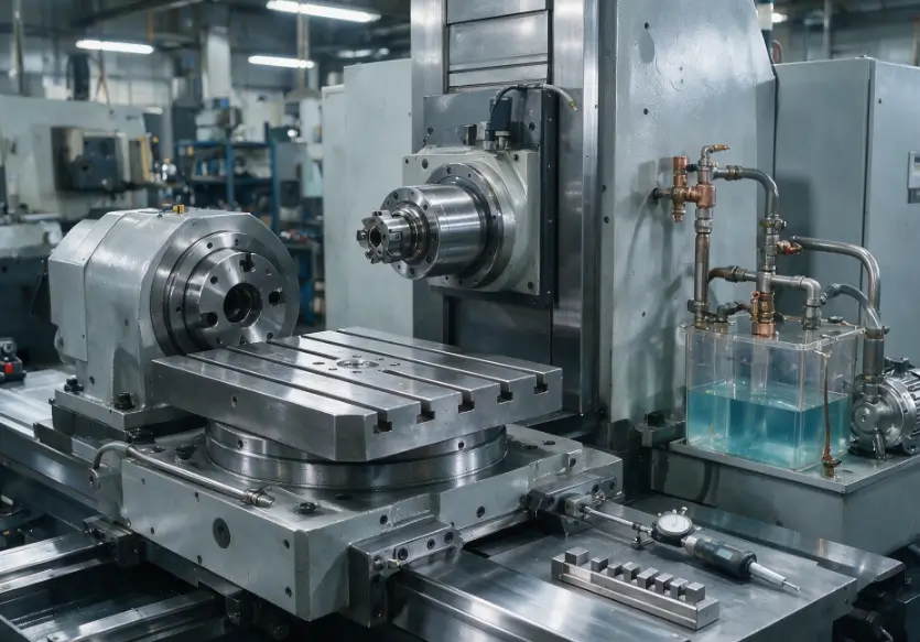
II. Core Solution 1: Thermal Deformation Compensation — 3 Compensation Methods to Offset Temperature-Induced Errors
1. Software Compensation: Parameter Settings + Macro Programs for Precise Thermal Error Offset
Core Logic: Automatically adjusts axis positioning values based on temperature changes via CNC system parameters or macro programs; compatible with mainstream systems including FANUC, Siemens, and Mitsubishi;
Practical Steps (Using FANUC 31i-Model A as an example):
Enable thermal deformation compensation: Set parameter 1605#0 to 1 (thermal compensation active), configure compensation axes via parameter 1606 (select all X/Y/Z/B axes);
Set temperature monitoring points: Input sensor IDs for parameters 1610-1613 (one each for spindle, worktable, and ambient);
Input compensation coefficients: Configure based on measured data (e.g., Z-axis compensates -0.0012mm per 1°C spindle temperature rise; input corresponding coefficients for parameters 1620-1623);
Macro program example (ambient temperature compensation):
plaintext
O0001 (Thermal Compensation Macro)
#100=READ_TEMP(3) (Read ambient temperature sensor 3 data)
#101=(#100-20)*0.0008 (Compensate 0.0008mm per 1°C deviation from 20°C baseline)
G65 H01 P#5221 Q#101 (X-axis compensation)
G65 H01 P#5222 Q#101 (Y-axis compensation)
M99
Applicable scenarios: Continuous spindle operation generating heat, ambient temperature fluctuations (within ±3°C). Compensation reduces errors by 60%-70%.
2. Hardware Optimization: Cooling + Thermal Insulation to Reduce Thermal Deformation at Source
Spindle Cooling Upgrade:
Enable spindle constant-temperature cooling system (setpoint 20±1°C), flow rate ≥8L/min, pressure ≥0.3MPa;
Install thermal insulation cover on spindle housing to minimize heat transfer to bed (bed temperature fluctuation ≤0.5°C after insulation);
Work Table Cooling Optimization:
Integrate cooling channels within the indexing mechanism, circulating temperature-controlled oil (22±1℃) to reduce friction heat from gear meshing;
Adopt dual-path rotary joints (separate lubrication + cooling) to prevent localized heating from coolant leakage;
Environmental Temperature Control:
Install central air conditioning in the workshop (avoid direct airflow on machines), maintaining temperature at 20±2℃ and humidity 40%-60%;
Heat-generating equipment (e.g., welders, heaters) must be kept ≥1.5m away from the machine tool.
3. Operating Procedures: Preheating + Machining Rhythm for Stable Thermal Equilibrium
Mandatory Startup Preheating Protocol:
After powering on, idle the spindle for 5 minutes (3000 rpm);
Low-speed rotation of worktable + reciprocating movement of all axes (speed 30m/min) for 10 minutes;
Before machining the first part, measure positioning error with a standard bar; confirm ≤0.004mm before production;
Machining Rhythm Control:
Avoid prolonged high-speed idle spindle rotation (single idle run ≤3 minutes); reduce to 1000rpm during idle periods;
During batch production, halt operation for 5 minutes every 2 hours to allow thermal equilibrium reset and minimize cumulative errors.
4. Compensation Parameter Templates for Different Heat Sources
| Heat Source Types | Compensation Methods | Core Parameter Settings (FANUC System) | Compensation Effect (Error Reduction Rate) |
| Spindle high-speed heating | Software Compensation | Parameter 1623 (Z-axis compensation coefficient) = -0.0015 mm/°C | 70% |
| Work table indexing heating | Hardware Cooling + Software Compensation | Coolant Temperature 22°C, Parameter 1624 (B-axis Compensation Factor) = -0.0009 mm/°C | 65% |
| Ambient temperature fluctuations | Macro Program Compensation | Compensation per °C: 0.0008 mm (X/Y-axis) | 60% |
| Tool cutting heating | Center Water Outlet Cooling | Pressure 25-30 bar, Flow Rate ≥5 L/min | 50% |
III. Core Solution 2: Workbench Maintenance Practices — 5 Key Modules to Ensure Indexing/Rotation Accuracy
1. Indexing Mechanism Maintenance: Gear Disk + Gear Set — The “Core Transmission” for Precision
Cleaning Procedure (Weekly):
Rotate workbench to limit position; use compressed air (0.4MPa) to blow out chips from gear disk gaps;
Dip a brush in gear cleaner (e.g., Shell Omala cleaner) and scrub the gear disc tooth surfaces (avoid scratching);
After drying, apply high-temperature grease (e.g., SKF LGMT 3, 120°C temperature resistance) to fill one-third of the tooth clearance;
Clearance Adjustment:
Measure the gear disc meshing clearance with a feeler gauge (standard ≤0.002mm). If out of tolerance, adjust the locking bolt (each 1/4 turn reduces clearance by 0.001mm).
Gearbox Oil Replacement (every 6 months): Use synthetic gear oil (viscosity 68cSt/40°C), filling to the oil sight glass level (1/2 to 2/3 mark).
2. Workbench Guide Rail and Locking Mechanism Maintenance
Guide Rail Maintenance:
Before daily operation, clean guide rail surfaces with a lint-free cloth and apply guide rail oil (recommended: Mobil SHC 632, viscosity 32cSt);
Inspect guide rail covers for damage (damage allows chips to enter and scratch rails). Measure guide rail straightness monthly with a dial indicator (≤0.003mm/m).
Locking Mechanism Maintenance:
Weekly check locking cylinder pressure (standard 3.5-4MPa). Adjust relief valve if pressure is insufficient.
Remove locking brake pads and clean friction surfaces (remove oil/chips). Replace brake pads if wear exceeds 0.5mm;
Practical Test: After locking the worktable, measure end face runout with a dial indicator (≤0.002mm) to ensure no looseness.
3. Rotary Joint and Piping Maintenance
Leak Inspection (Daily Pre-shift):
Inspect rotary joint connections for coolant/lubricant leaks. Tighten seal nuts for minor leaks; replace seals for severe leaks (recommended material: nitrile rubber for oil and high-temperature resistance).
Pipe Cleaning (Monthly):
Disassemble cooling/lubrication pipes, blow out internal debris with compressed air, inspect pipes for aging (aged pipes may rupture, causing oil/fluid supply interruption);
Maintenance Standard: Rotating joint operates smoothly without binding, pipe pressure loss ≤0.05MPa, ensuring continuous and stable cooling/lubrication.
4. Common Workbench Fault Emergency Troubleshooting
| Fault Symptoms | Troubleshooting Steps | Solutions | Post-Recovery Accuracy Verification |
| Workbench fails to rise | 1. Check hydraulic system pressure (whether ≥3MPa);2. Inspect lift cylinder sensor;3. Check for blockages in oil lines | 1. Adjust the relief valve to standard pressure; 2. Clean the sensor; 3. Clear the oil passages | Lifting Repeatability ≤ 0.002 mm |
| Rotation stutters | 1. Verify adequate guide rail lubrication;2. Measure gear disc clearance;3. Check for rotation joint jamming | 1. Refill guide rail oil; 2. Adjust the gear disc clearance; 3. Replace the rotary joint bearings | Rotational Resistance ≤ 5 N, no abnormal noise |
| Indexing error exceeds tolerance | 1. Measure indexing accuracy using laser interferometer;2. Inspect gear disc wear;3. Verify thermal compensation parameters | 1. Replace worn gear discs; 2. Recalibrate compensation parameters; 3. Adjust the locking mechanism | Indexing Error ≤ 0.003 mm |
5. Maintenance Schedule and Tool List
Daily Maintenance (5 minutes): Clean guide rails + rotary joints, check locking pressure, observe for leaks;
Weekly Maintenance (30 minutes): Clean and lubricate gear discs, inspect guide rail clearance, clean locking brake pads;
Monthly Maintenance (1 hour): Clean piping, lubricate rotary joint bearings, measure guide rail straightness;
Essential Tools: Feeler gauge (0.001-0.01mm), dial indicator (accuracy 0.001mm), laser interferometer (e.g., Renishaw XL-80), torque wrench (accuracy ±1N・m).
IV. Accuracy Calibration and Monitoring: Ensure error stability within ±0.005mm
1. Calibration Tool Selection: Professional Tools + Simple Verification
Core Calibration Tools:
Laser interferometer (measures positioning accuracy and repeatability, accuracy ±0.5ppm);
Ball bar (detects dynamic accuracy, e.g., roundness error ≤0.004mm);
Level (accuracy 0.02mm/m), measures worktable levelness and bed levelness;
Simple Verification Tools:
Standard bar (accuracy ±0.001mm, e.g., φ50×300mm), measuring diameter deviation at different positions;
Square box (accuracy 0.002mm), detecting worktable indexing perpendicularity.
2. Calibration Procedure (Quarterly, Mandatory)
Environmental Preparation: Maintain workshop temperature at 20±1°C; preheat machine tool for 20 minutes;
Geometric Accuracy Calibration:
Calibrate bed levelness using spirit level (≤0.02mm/m);
Measure X/Y/Z-axis straightness (≤0.003mm/m) and perpendicularity (≤0.004mm) using laser interferometer;
Positioning Accuracy Calibration:
Set measurement intervals (1 point per 50mm), measure positioning error and repeatability error for each axis;
Generate error curves via software and compensate using system parameters (e.g., FANUC parameter 1815);
Work Table Indexing Accuracy Calibration:
Measure B-axis indexing error using a laser interferometer (1 point per 90°). Adjust gear disc clearance or compensation parameters if out of tolerance;
Test Cutting Verification:
Machine a standard test specimen (100×100×50mm box with 4 side holes);
Measure hole position accuracy (≤0.005mm), perpendicularity (≤0.004mm), and parallelism (≤0.003mm).
3. Daily Monitoring: Real-time Interception of Deviation Risks
First-piece inspection: Before each batch production, measure 3 critical dimensions; proceed only if error ≤0.004mm;
Process sampling: After every 20 parts processed, inspect 1 piece. If deviation exceeds 0.005mm, halt production for inspection (prioritize checking thermal deformation and worktable clamping);
Data logging: Maintain a Precision Monitoring Record Form to document daily first-piece deviations and calibration data. Intervene promptly upon detecting trend anomalies (e.g., consecutive 3-day increasing deviations).
V. Practical Case Study: Precision Optimization at a Box Manufacturing Plant
1. Original Issue
Equipment: Horizontal machining center (FANUC system, 15kW spindle, 4-station worktable);
Pain Points: After 3 consecutive hours of machining, positioning error increased from ±0.003mm to ±0.012mm, worktable indexing deviation reached 0.009mm, and case hole coaxiality deviation caused 10% scrap rate;
Core Causes: Uncompensated spindle thermal deformation, worn worktable gear disc (0.004mm backlash), ±5℃ workshop temperature fluctuations.
2. Optimization Plan
Thermal Deformation Compensation: Enable system thermal compensation, set spindle compensation coefficient to -0.0015mm/℃, and implement environmental compensation macro program;
Workbench Maintenance: Replace worn gear disc (clearance adjusted to 0.0015mm), upgrade spindle constant-temperature cooling system;
Environmental Optimization: Install central air conditioning in workshop, maintaining temperature at 20±2℃;
Operational Standards: Implement 15-minute preheating before startup, with 5-minute shutdowns every 2 hours.
3. Optimization Results
Positioning Error: Stabilized within ±0.005mm (previously ±0.012mm), reducing error by 58%;
Scrap Rate: Decreased from 10% to 2%, saving 32,000 yuan monthly in rework losses;
Downtime: Precision-related stoppages reduced from 1.2 hours/day to 0.2 hours/day, boosting efficiency by 16%.
VI. Common Accuracy Maintenance Pitfalls and Avoidance Guide
1. Pitfall 1: Relying solely on software compensation while neglecting hardware cooling
Issue: Thermal deformation compensated only through parameters, but spindle cooling system inactive, causing inconsistent compensation (error fluctuation ±0.003mm);
Avoidance: Software compensation must be paired with hardware cooling. Constant-temperature spindle cooling + environmental temperature control are fundamental; otherwise, compensation parameters will fail due to unstable heat sources.
2. Misconception 2: Workbench maintenance focuses only on cleaning, not gap adjustment
Issue: Regular workbench cleaning without inspecting gear disc gaps caused indexing error to increase from 0.002mm to 0.008mm, yet the root cause remained unknown;
Avoid Pitfalls: After each cleaning, measure gear disk clearance with a feeler gauge (≤0.002mm). Adjust immediately if out of tolerance—clearance is critical for indexing accuracy.
3. Misconception 3: Skipping warm-up before machining
Issue: To save time, machining starts immediately after power-up, causing first-piece errors of 0.009mm requiring rework.
Avoid pitfalls: Preheating is critical for stability. A 15-minute warm-up achieves thermal equilibrium, reducing first-part errors by 70% and ultimately saving rework time.
4. Misconception 4: Believing “High-Precision Machines Require No Calibration”
Issue: After one year of use without calibration, positioning error increased from ±0.003mm to ±0.008mm, mistakenly attributed to equipment quality;
Avoidance: Even high-end machines experience minor deformation in bed and guideways due to prolonged stress. Quarterly calibration ensures precision remains stable.
VII. FAQ: Common Issues in Maintaining Accuracy for Horizontal Machining Centers
Q: How do I set thermal deformation compensation parameters for Siemens systems, which differ from FANUC?
A: Siemens systems use “MD32700 (Positioning Accuracy Compensation)” and “MD32710 (Thermal Deformation Compensation Coefficient)” for configuration. The core logic remains consistent: first measure the temperature-error curve, then input the corresponding coefficients. Contact the machine tool manufacturer for a dedicated parameter template, or reference the macro program approach in this document to write PLC programs.
Q: How can small and medium-sized enterprises perform simplified accuracy calibration without a laser interferometer? A: Use a “standard bar + dial indicator” combination: 1. Secure the standard bar to the worktable and measure diameter deviations at different positions (5 points each on X/Y/Z axes) using the dial indicator; 2. Repeat measurements after rotating the worktable 90°; 3. If errors exceed ±0.005mm, adjust thermal compensation parameters or worktable clearance correction to achieve accuracy within ±0.006mm, sufficient for general-purpose part machining.
Q: How to permanently resolve frequent leakage in the worktable rotary joint? A: 1. Replace with a high-quality rotary joint (recommended brand: Deublin, dual-seal design); 2. Adjust pipeline pressure (cooling ≤0.3MPa, lubrication ≤0.4MPa) to prevent seal damage from excessive pressure; 3. Clean internal bearings monthly and apply high-temperature grease to extend seal lifespan.
Q: Poor thermal deformation compensation when machining large parts (>1000mm). What should be done? A: 1. Add temperature monitoring points (one sensor at each end of the bed) for segmented compensation; 2. Allow thermal deformation allowance during part clamping (0.005mm per 1000mm); 3. Adopt a “segmented machining + intermediate calibration” mode, stopping every 500mm to measure and correct errors.
Conclusion
The core logic for maintaining precision in horizontal machining centers is dual-driven by “thermal deformation control + worktable maintenance” — offsetting thermal errors through software compensation, hardware cooling, and operational standards, while ensuring worktable indexing and rotational accuracy via cleaning, lubrication, and calibration. This combination stabilizes positioning errors within ±0.005mm and extends equipment precision lifespan by over 2 times. MINNUO horizontal machining centers reinforce this logic from the design stage: their standard-equipped spindle constant-temperature cooling system (temperature fluctuation ≤0.5℃) and high-precision backlash-eliminating gear discs (factory-set meshing clearance ≤0.0015mm) lay an inherent foundation for thermal deformation control and worktable precision maintenance, ensuring more stable and enduring precision retention.
To facilitate rapid implementation of these strategies in the workshop, we have compiled practical tools such as the Thermal Deformation Compensation Parameter Template and Work Table Maintenance Checklist. MINNUO customers can additionally obtain the brand-exclusive Precision Retention Adaptation Guide. This guide customizes parameters like thermal compensation coefficients and gear disc clearance maintenance thresholds based on MINNUO horizontal machining centers' spindle performance and worktable structural specifications. It further streamlines operational workflows, ensuring every MINNUO machine efficiently achieves the “positioning error within ±0.005mm” target.
If you are pursuing precision maintenance optimization, begin today with preheating and worktable status checks, followed by gear disc maintenance and thermal compensation activation this week. Throughout this process, MINNUO's professional technical team and nationwide service network will provide comprehensive support. Contact MINNUO anytime for complimentary precision diagnostics. Leveraging our technical expertise in horizontal machining center accuracy control, we can stabilize positioning error within ±0.005mm within three months, making your MINNUO horizontal machining center a reliable backbone for high-precision production in your workshop.
 Email
Email sales1: +86 15312799623