How does a CNC system control machine movements?
As a practitioner with many years of experience in the machine tool industry, I am often asked how the CNC system achieves precise control of machine tool motion.
The CNC system parses machining instructions, converts the target position into a motion trajectory, then uses the servo system to transform electrical signals into precise mechanical movement, and employs feedback correction to ensure machining accuracy.
Next, I will break down the CNC system's motion control mechanism from the perspectives of control principles, implementation steps, and key technical modules, combining practical work experience.
I.CNC System Motion Control Principles Overview
The core mission of a CNC (Computer Numerical Control) system is to convert digital machining instructions into coordinated mechanical motion across the machine axes. The control principle can be summarized as a closed-loop control cycle: "Digital Instructions - Logic Processing - Physical Drive - Feedback Correction". Specifically:
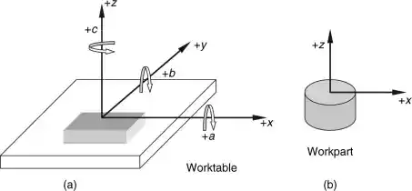
1.Coordinate System Transformation: Converting the 3D model coordinates of the part design into motion trajectory coordinates within the machine's coordinate system.
2.Trajectory Interpolation Calculation: Using mathematical algorithms to fit a motion path that meets the required precision.
3.Servo Drive Control: Converting electrical signals into motor speed and torque output.
4.Real-Time Error Compensation: Using sensor feedback to calibrate motion precision.
This process is akin to the precise meshing of gears in a fine-tuned clock, with each step requiring micron-level control precision. For example, in a precision mold processing project I was involved in, even a 0.01mm control error could result in the entire part being scrapped, underscoring the importance of control principles.
II.Key Steps in the Control Process
1.Processing Instruction Input and Parsing
Once engineers import the written G-code program into the CNC system, the system first performs syntax checking and code translation:• Recognizes function commands such as G00 rapid positioning, G01 linear interpolation, etc.
• Extracts key parameters like coordinate data (X/Y/Z target positions) and feed speed (F value).
• Establishes the transformation relationship between the workpiece coordinate system and the machine tool coordinate system.
During one of my debugging experiences, the machine exhibited abnormal motion due to an error in the coordinate system definition in the program, which highlights the critical importance of precise instruction parsing.
2.Trajectory Planning and Interpolation Calculation
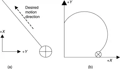
Point Control Scenario (e.g., CNC drilling machine): Directly calculates the shortest displacement path using a rapid positioning algorithm.
Profile Control Scenario (e.g., mold processing):
• Performs linear interpolation for straight-line trajectories.
• Executes arc interpolation for circular trajectories.
• Uses spline interpolation for freeform curve trajectories.
For example, when processing automotive body mold parts, the CNC system must perform tens of thousands of interpolation calculations per second to ensure the tool path perfectly matches the CAD model. These high-frequency calculations rely on specialized calculation chips embedded in the system, such as FANUC's nanometer-level interpolation technology, which achieves control precision of 0.001mm.
3.Servo System Drive Control
The position commands generated by the interpolation calculations need to be converted into mechanical movement via the servo system:Signal Amplification: The ±10V analog signals or pulse signals output by the CNC are amplified by the servo driver to the required power for the motor.
Motor Control:
• AC servo motors achieve high-precision speed control.
• Linear motors directly drive the worktable to eliminate transmission chain errors.
Feedback Closed-Loop:
• Semi-closed loop: Motor angle detection via an encoder (typically 20-bit absolute encoders with a resolution of 0.01μm/pulse).
• Full closed-loop: Position detection via linear scales (precision up to 0.1μm).
In precision machining scenarios, we typically use full closed-loop control. For example, I once debugged a high-precision grinding machine that achieved a machining accuracy of 0.5μm with feedback control from Renishaw linear scales, which could only be achieved through the precise cooperation between the servo system and the CNC.
4.Error Compensation and Precision Optimization
During actual machining, factors such as mechanical transmission errors and thermal deformation can affect motion precision. The CNC system employs multiple compensation mechanisms to ensure machining accuracy:• Backlash Compensation: Eliminating transmission backlash from ball screw-nut pairs.
• Pitch Error Compensation: Segmenting compensation for screw machining errors.
• Thermal Deformation Compensation: Real-time correction of axis thermal expansion errors using temperature sensors.
• Tool Radius Compensation: Automatically offsetting the tool center trajectory using G41/G42 commands.
III.Key Technical Modules Analysis
1.Hardware Architecture: The Physical Carrier of Control Signals
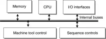
• Central Processing Unit: Mainstream systems use multi-core CPUs and specialized motion control chips (such as Mazak's MAZATROL processors).
• Position Control Module: Integrates D/A conversion and pulse generation functions, enabling high-speed position command output (typically output frequency above 1MHz).
• Input/Output Interfaces: Supports multiple communication methods like RS232, USB, Ethernet, etc., for program transmission and machine status monitoring.
2.Software System: The Core Algorithms of Control Logic
• Real-Time Operating System (RTOS): Ensures nanosecond-level response for interpolation calculations, servo control, and other tasks.
• Motion Control Algorithm Library: Includes advanced algorithms such as PID control, feedforward control, and robust control to optimize the dynamic characteristics of the servo system.
• Human-Machine Interface: Supports graphical programming, machining simulation, and status monitoring, reducing the complexity of operation.
IV.Different Control Modes and Their Application Scenarios
Control Mode | Technical Features | Typical Applications | Accuracy Level |
Point Control | Only controls the endpoint, no path planning | CNC drilling machine, coordinate measuring machines | ±0.05mm |
Linear Control | Controls linear trajectory and feed speed | CNC lathes, milling machines for flat machining | ±0.01mm |
Profile Control | Multi-axis coordinated control of complex curves | Machining centers, five-axis machines | ±0.001mm |
For five-axis simultaneous machining, it is necessary to control three linear axes (X/Y/Z) and two rotary axes (A/C). The CNC system must calculate the tool axis angle and the normal angle to the machining surface in real time, which poses a high level of complexity for the control algorithm.
Conclusion
From point control to five-axis simultaneous control, CNC system motion control is essentially the deep integration of information technology and mechanical engineering. As practitioners, we must not only understand the underlying mathematical principles and control algorithms but also accumulate experience in parameter optimization during actual debugging.
If you are facing difficulties in selecting CNC systems or have encountered precision issues that cannot be resolved during equipment debugging, feel free to contact us at Minnuo. Our professional technical team will provide detailed answers and personalized solutions to help you efficiently implement your production requirements.
 Email
Email sales1: +86 15312799623