How to Diagnose and Correct Spindle Speed Abnormalities in CNC Machining Centers?
Have you ever encountered spindle speed abnormalities in your machining center? For example, it doesn’t speed up when it should, doesn’t slow down when necessary, or fluctuates unexpectedly. These issues can lead to serious consequences: at best, part dimensions go out of tolerance and tool wear accelerates; at worst, there’s mass scrapping of parts or even machine damage.
Many operators may panic in such situations—either repeatedly adjusting parameters or blindly replacing components—resulting in unresolved issues and wasted production time. Diagnosis should follow a path from simple to complex, from external to internal, gradually checking electrical, mechanical, and control systems, using alarm messages and measurement tools to locate the root cause. Correction should target the fault through component repair or replacement, parameter adjustment, or optimization of external conditions to restore proper spindle speed.
There’s always a reason behind speed abnormalities. Today, let’s explore their causes and solutions together.
I. What Are the Effects of Spindle Speed Abnormalities?
Spindle speed abnormalities may seem like just an issue of “inaccurate speed,” but the impact in actual machining is very real:
When speed is too high, cutting force suddenly increases, especially for carbide tools, which can chip easily. The cutting temperature spikes, accelerating tool wear and potentially burning the surface of the workpiece.
When speed is too low, cutting force is insufficient, and the material is prone to extrusion and deformation. The surface may show visible chatter or tool marks, making it impossible to guarantee precision. Additionally, machining time increases and efficiency drops significantly.
When speed fluctuates, dimensional accuracy becomes unstable. For example, during face milling, speed variations lead to inconsistent cutting depths, resulting in flatness out-of-tolerance. During turning, it may cause a “bamboo pattern” on cylindrical surfaces, rendering the part scrapped.
II. Common Causes of Spindle Speed Abnormalities in CNC Machining Centers
Spindle speed abnormalities are not caused by a single factor. Troubleshooting should be conducted across four areas: electrical, mechanical, control system, and external environment.
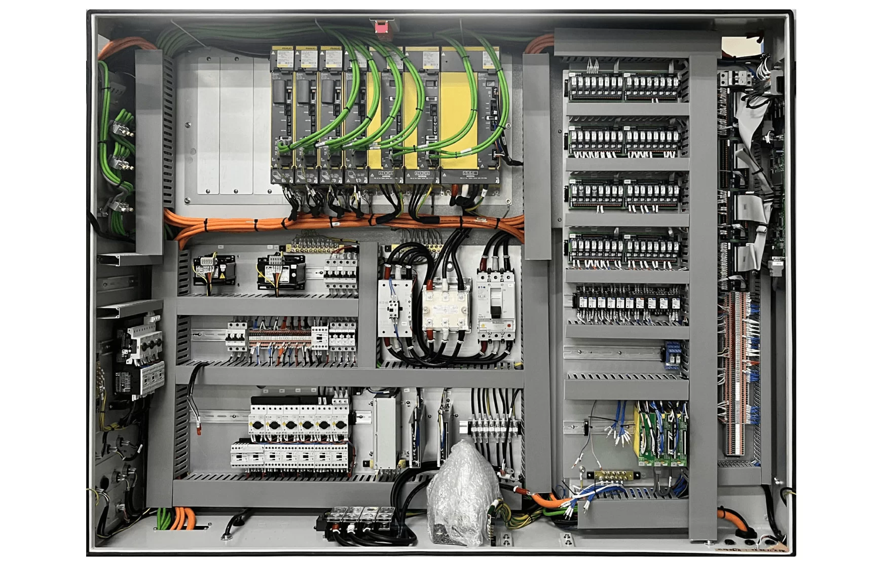
(1) Electrical System Failures:
The electrical system provides the spindle’s power, so any issues here will directly impact the spindle speed.
Spindle Drive Motor Issues:
•Motor winding short circuits, open circuits, or poor grounding can result in insufficient output power, causing the spindle to fail to reach the set speed—more pronounced under load.
•Rotor faults (e.g., broken squirrel cage bars) can cause speed instability, especially when the load changes. This is often accompanied by unusual noises.
•Worn motor bearings increase rotational resistance, causing a gradual drop in speed, along with increased vibration and heat in the motor housing.
Spindle Drive Faults:
•Incorrect drive parameter settings, such as a low maximum speed limit or inappropriate acceleration time, can lead to “limited” speeds or abrupt speed changes during startup.
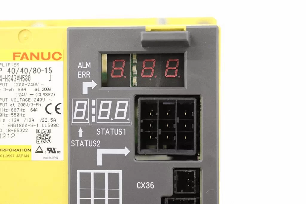
•Internal power module failure in the drive may prevent normal drive signals from being output. The motor might not turn, or the speed could be far below the set value. Typically, the drive panel will show an alarm light.
•Drive cooling system failures (e.g., non-functioning fan or blocked heat sink) can cause overheat protection to activate, leading to sudden deceleration or shutdown of the spindle.
Electrical Connection Issues:
•Loose contacts, broken cables, or aging insulation between the motor and the drive can cause unstable current delivery, resulting in speed fluctuations.
•Loose connections in the control loop may distort the speed command signal, causing the spindle to not respond or respond with delays.
•Oxidized relay or contactor points can cause intermittent power delivery, resulting in fluctuating spindle speed.
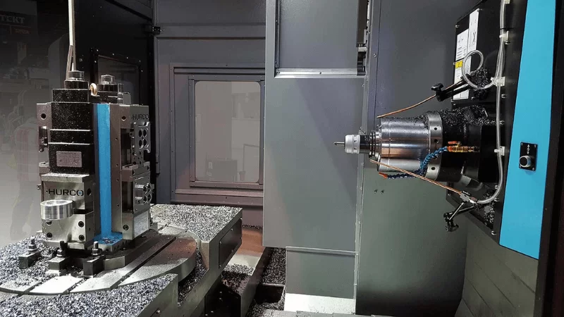
(2) Mechanical Transmission System Failures:
Mechanical components transmit power from the motor to the spindle. Any blockage here will certainly affect spindle speed.
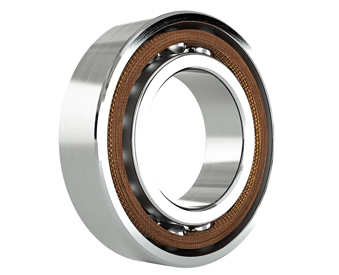
Spindle Bearing Failures:
•Bearings are the core support for spindle rotation:
•Bearing wear, poor lubrication, or damage increases friction, significantly reducing speed, especially during high-speed operation.
•Improper bearing preload (too tight or too loose) causes problems: too loose leads to speed fluctuations, too tight increases resistance, preventing speed buildup and accelerating wear.
Transmission Mechanism Problems:
Transmission Type | Common Faults | Impact on Speed |
Belt Drive | Insufficient tension (slipping), aging/cracks, worn or misaligned pulleys | Sudden speed drops, large fluctuations; in severe cases, spindle won’t rotate |
Gear Drive | Excessive/inadequate backlash, worn or broken gear teeth | Irregular speed changes, with “clunking” sounds |
Couplings | Loose, damaged, misaligned installation | Periodic speed fluctuation, noticeable vibration |
Spindle Box Internal Failures:
Issues can also arise inside the spindle box. Insufficient or degraded lubricant can result in poor lubrication of gears and bearings, increasing friction and gradually reducing speed. If chips or foreign debris enter the box and jam the spindle, the speed may suddenly drop or even stop completely.
(3) Control System and Parameter Setting Issues:
The control system is essentially the "brain" of the spindle. If commands or parameters are wrong, spindle speed will naturally become abnormal.
CNC System Parameter Errors:
•Incorrect spindle override settings can cause proportional deviations between actual and set speeds (e.g., if override is set to 50%, actual speed will only reach half the command).
•A low setting on the maximum spindle speed parameter will "lock" the upper speed limit. Even if the program commands higher speed, the spindle won’t accelerate.
•Incorrect spindle gear change parameters may cause gear shift anomalies, such as staying in low gear even when high speed is needed.
Program Command Issues:
Program errors can also cause problems. For example, an incorrect S code in the machining program (e.g., S300 instead of S3000) results in incorrect speed. Sometimes, the speed command is given before the spindle start command (M03), causing the spindle to not respond at all.
Feedback System Failures:
•If the spindle encoder (optical or magnetic) is damaged or its signal is lost, closed-loop speed control fails, and the system cannot sense actual spindle speed, causing speed to go out of control.
•Loose coupling between encoder and spindle causes feedback mismatch, leading the system to "misjudge" and make unnecessary speed adjustments, resulting in fluctuations.
(4) External Environment and Load Factors:
Aside from the machine itself, external conditions can also cause spindle speed issues.
Excessive Load:
•Uneven stock removal may cause sudden high loads during cutting, exceeding spindle capacity and resulting in speed drops.
•Dull tools or improper cutting parameters (e.g., excessive feed rate) increase cutting resistance, preventing the spindle from "pulling through" and causing natural speed reduction.
External Interference:
Power grid voltage fluctuations or nearby equipment (welding machines, induction furnaces) causing electromagnetic interference can disrupt spindle drive performance, leading to speed fluctuations.
Cooling and Lubrication System Abnormalities:
If the cooling system fails (e.g., pump not working, pipe blockage), the spindle may overheat and trigger protection mechanisms that limit speed. Inadequate lubrication increases friction in drive components, leading to speed reduction.
III. Diagnosis Methods for Spindle Speed Abnormalities
Diagnosing spindle speed issues should follow the principle of “from simple to complex, from external to internal,” gradually narrowing down the cause.
(1) Initial Inspection and Data Collection:
Start by observing and measuring basic conditions:
•Record the symptoms: No response at startup? Sudden deceleration during operation? Speed fluctuation in specific ranges (e.g., 1000–2000 rpm)?
•Determine the timing: Is the issue present under load but not under no-load? Did it appear after tool or workpiece changes?
•Check basic status: Any abnormal noise or vibration in the spindle box? Is oil temperature too high (should be ≤60°C)? Any alarms on the drive or CNC system?
•Data collection: Use a tachometer to measure actual speed and compare with the set value; log the deviation. Check spindle load rate (normally ≤80%) to identify potential overload.
(2) Systematic In-Depth Diagnosis
Electrical System Diagnosis:
Begin with drive alarm codes, which offer important clues. For example, overcurrent alarms may indicate motor short circuits or failed drive power modules. Overheat alarms require checking if fans are working or if heat sinks are clogged.
Use a multimeter to measure winding resistance; the three-phase resistances should be close (deviation ≤5%). Large differences may suggest short or open circuits. Use a megohmmeter to check insulation resistance—it should be ≥5 MΩ between motor casing and windings.
Inspect electrical connections carefully. Are cable joints or terminals loose or oxidized? Use an oscilloscope to verify that speed command voltage (usually 0–10V) and encoder feedback signals are stable, with no signal loss.
Mechanical System Diagnosis:
Spindle idle test: Disconnect the spindle from the drive mechanism (e.g., remove belt), and run the motor alone. If speed is normal, the fault lies in mechanical components; if not, the issue is electrical or control-related.
Transmission component inspection: For belt drives, check tension (deflection of 10–15mm is normal), apply chalk to detect slippage. For gears/couplings, check mesh condition and listen for abnormal sounds (e.g., “clunking” suggests broken gear teeth; “buzzing” may indicate bearing wear).
Bearing and lubrication checks: After 30 minutes of operation, use an infrared thermometer to measure bearing housing temperature (should not rise more than 40°C). Check oil level and quality. Disassemble and inspect bearings if necessary.
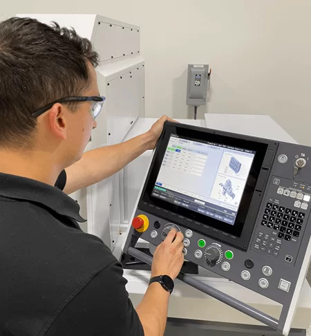
Control System Diagnosis:
•Check parameters in the CNC system. Review max spindle speed, override, gear change settings—compare with the manual to see if they've been altered.
•Use MDI mode to test a command like “M03 S1000” and observe if the spindle runs stably at 1000 RPM to rule out program errors.
•Inspect the encoder: ensure secure connection and intact cables. Use an oscilloscope to observe encoder output—signals should be clean square waves. If the waveform is broken, the encoder may be faulty or the signal lost.
IV. Repair Methods for Spindle Speed Abnormalities
Efficient problem-solving requires targeted repairs based on diagnostic results.
(1) Electrical System Repairs:
•Motor faults: Rewind the motor or replace it; replace worn bearings with the same model and apply special grease (e.g., lithium-based for high-speed bearings).
•Drive faults: Reset incorrect parameters using the manual or restore factory settings if needed; replace damaged power modules (ensure power is off and avoid static damage); clean heat sinks and replace fans.
•Connection faults: Tighten any loose connections (power off first); replace broken or aged cables with same-spec replacements (ensure shielding is grounded); clean or replace oxidized relay/contact points.
(2) Mechanical System Repairs:
•Bearing issues: Replace worn or damaged bearings and adjust preload according to the manual (usually via nuts or spacers); if lubrication is inadequate, refill or replace spindle oil (e.g., ISO VG32) and clear blocked lube paths.
•Transmission issues: Adjust belt tension if slipping; replace if aged. Fix gear backlash or replace worn/broken gears. Tighten or replace loose/damaged couplings, ensuring coaxial alignment (deviation ≤0.1mm).
•Spindle box faults: Refill lubricant, replace degraded oil; remove internal debris and unblock oil paths.
(3) Control and External Issue Handling:
•Parameter and program errors: Reset incorrect parameters according to the manual; correct S code errors and optimize speed-switching logic (e.g., add M05 stop command before switching).
•Feedback issues: Replace faulty encoder with the same model (match signal type); tighten loose connections for stable signals.
•External factors: Reduce load by optimizing cutting parameters (lower feed rate, sharper tools), ensure even stock removal; install voltage stabilizers and add electromagnetic shielding; repair coolant pumps and clear lubrication pipes to ensure adequate supply.
V. Preventive Measures
Prevention can eliminate many potential issues. Routine maintenance is crucial:
•Weekly: Check belt tension, ensure electrical cabinet fans are working, and verify spindle box oil level.
•Monthly: Measure motor insulation resistance, inspect encoder connections, replace filters.
•Quarterly: Replace spindle box lubricant, check bearing temperature rise, and calibrate encoder signals.
Environmental factors also matter. Keep the workspace clean—avoid dust and oil entering the spindle box and electrical cabinet. Maintain stable grid voltage and stay away from strong EMI sources like welders.
In humid areas, install dehumidifiers in electrical cabinets; in dusty workshops, clean with compressed air regularly.
Conclusion
Diagnosing spindle speed abnormalities requires a multi-dimensional approach across electrical, mechanical, and control systems. The key is: observe symptoms, test step-by-step, and apply targeted repairs. Good routine maintenance can significantly reduce failure rates.
If you encounter complex issues, it's more efficient to contact a professional technical team. As a solution-oriented machine tool manufacturer, Minnuo provides free consultation—our expert team is always ready to help you solve spindle-related issues and keep your machining smooth!

 Email
Email sales1: +86 15312799623