How to Improve Cutting and Grooving Efficiency on CNC Lathes?
After spending enough time on the shop floor, you’ll realize that the cutting and grooving efficiency of CNC lathes is often the key factor in speeding up the production line. Sometimes, even with good equipment and tools, the expected output just isn’t there. Upon closer inspection, it often boils down to overlooked optimizations in the details.
The core of improving cutting and grooving efficiency lies in three aspects: choosing the right tool, setting reasonable parameters, and optimizing the programming path. Coupled with stable clamping methods and good machine condition, efficient and stable machining performance can be achieved.
Let’s talk today from the perspective of actual production and walk through how to systematically boost the efficiency of these two critical operations. Hopefully, this will help you if you’re exploring ways to enhance productivity.

I. What Are the Challenges in Improving Cutting and Grooving Efficiency?
Low efficiency in cutting and grooving is rarely caused by a single factor. It involves tools, parameters, programming, machine conditions, and even the workpiece itself—all of which interact. For example, excessive cutting force can lead to vibration, which in turn accelerates tool wear, reducing processing speed and forming a vicious cycle.
Data clearly shows the impact of efficiency losses. Overall equipment efficiency (OEE)—the product of availability, performance, and quality—drops significantly when bottlenecks occur in cutting operations.
II. Choosing the Right Tool Is the First Gate to Efficiency
1. Tool Material
Tool material selection should be based on the material removal rate (MRR = 1000 × Vc × f × ap). The following are suitable tool materials for different workpieces:
Workpiece Material | Recommended Tool Material | Core Advantages |
45 steel (general steel) | Ultra-fine grain carbide (0.2–0.5 μm) | Better chipping resistance in interrupted cutting |
Hardened steel | Maintains >80% hardness at 1200°C | |
Aluminum alloy | Ultra-fine carbide / HSS | Low friction coefficient reduces built-up edge |
Cast iron | Coated carbide (TiCN) | High wear resistance and anti-chip build-up |
Superalloy | Ceramic tools / CBN | High temperature oxidation resistance for low-speed, high-feed cutting |
2. Optimizing Tool Geometry
Tool geometry significantly affects cutting force. For plastic materials, set rake angle as:
Rake angle = 10° + (Brinell hardness ÷ 200) × (–5°)
For example, for HB200 material:
Rake angle = 10 + (200/200) × (–5) = 5°
This angle reduces cutting resistance effectively.
Edge honing: Keep edge radius within 0.02–0.05 mm to reduce cutting force by 12–18%. Though often overlooked, it significantly extends tool life.
3. Coating

Modern nano multilayer coatings such as TiAlN and TiN (5–10 nm per layer) reduce friction coefficient below 0.3 and dramatically improve wear resistance. A simple quality test: coatings that withstand ≥80 N in scratch tests are considered qualified.
For high-speed dry cutting, choose AlCrN coating—it resists oxidation beyond 1100°C and performs well without coolant.
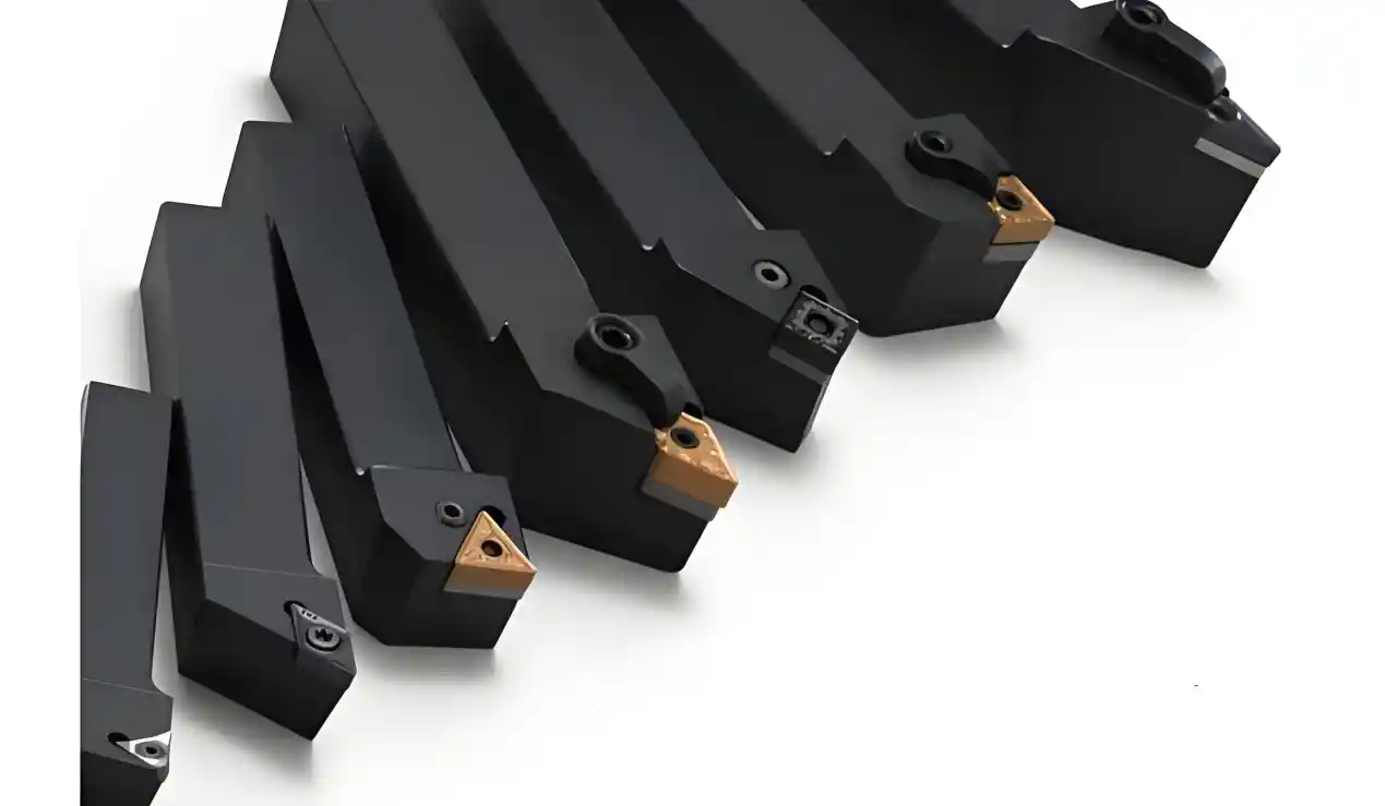
4. Stable Tool Holder, Less Vibration
Even the best tool won’t perform with an unstable holder. Rectangular tool holders have 40% higher torsional stiffness than round ones—especially beneficial in roughing. Keep tool overhang ratio below 4 to avoid low-frequency vibration.
Hydraulic chucks can keep radial runout under 0.002 mm and offer even clamping force—critical for high-speed precision machining.
III. Parameter Settings
Higher speed and feed don’t always mean higher efficiency. Parameters must balance quality and cutting speed.
1. Spindle Speed

Should align with tool life formula.

Excessive speed accelerates wear exponentially. Materials have critical cutting speeds (e.g., Ti alloy TC4 ≤ 60 m/min). Also, spindle speed (S) should not exceed power limit:
S ≤ (P × 60) / (2π × Tq)
Where:
T = tool life (min)
CT = material constant
Vc = cutting speed
n, m, p = influence indices of Vc, f, ap on tool life (e.g., n ≈ 0.1–0.3 for steel)
f = feed rate
ap= depth of cut
P = spindle power (kW)
Tq = cutting torque (Nm)
2. Feed Rate
Feed per tooth affects surface roughness (Ra):

For interrupted cuts (e.g., grooving near corners), reduce feed by 20–30%. Adjust dynamically based on tool wear.
Ra: Surface roughness (μm)
fz: Feed per tooth (mm/tooth)
rε: Tool cutting edge radius (mm)
3. Cutting Depth
Maximum depth:

Split into 2–3 layers for depths >3 mm (improves efficiency by ~15%). For grooves >5 mm wide, set depth to 1/3–1/2 of the width.
Where:
Here is the precise English translation of the text you provided:
apmax: Maximum cutting depth (mm)
T: Spindle output torque (N·m)
kp: Correction factor (1.1–1.2 for rigid machines, typically 1.0)
D: Workpiece diameter (mm)
kc: Cutting force coefficient (approximately 1800–2200 N/mm² for steel, 600–800 N/mm² for aluminum)
4. High-Speed Cutting
Requires Vc > 300 m/min, spindle > 8000 r/min. HSK holders must meet G2.5 balance at 20000 r/min. Compensate thermal error (add 0.015 mm/m for every 10°C rise).
Material | Critical Speed (m/min) | Recommended Feed (mm/r) | Suitable Depth (mm) |
45 Steel | 150–250 | 0.1–0.3 | 1–5 |
Stainless Steel | 80–150 | 0.08–0.2 | 0.5–3 |
Titanium Alloy | 30–60 | 0.05–0.15 | 0.3–2 |
IV. CNC Programming Optimization
Programs hold great potential for efficiency improvements. Often, machines aren’t slow—programs are inefficient.
1. Reduce Idle Travel
Idle time can be >20% of total cycle time. Use Dijkstra’s algorithm to plan shortest toolpaths and reduce idle moves by ~25%.
When using G00 (rapid move), set acceleration wisely: 50% for distances <50 mm prevents overshooting. Use G10 for dynamic tool offset changes to reduce tool change time.
2. Smoother Cutting Paths
Keep cuts continuous, avoid frequent stops. In arc interpolation, reduce feed by 30% when radius <5 mm to minimize impact. For groove retraction, a 45° diagonal is better than radial retraction—reduces friction and boosts efficiency by 40%.
3. Effective Cutting Cycles
Use layered cutting for deep grooves: 0.5–1 mm per layer, feed 0.1–0.15 mm/rev—excellent chip breaking. In G75 groove cycle: Q = 2–3 mm, Δd = 0.1 mm to prevent chip wrapping.
For threading, first pass depth = 0.12 × pitch, then reduce by √2 each time—ensures accuracy and faster cycle.
V. Machine Condition
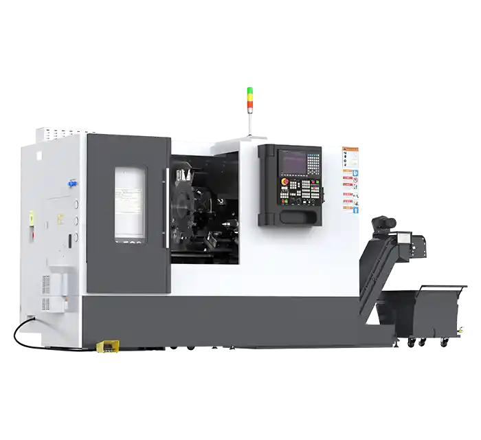
Good machine health is essential. From spindle to feed system and lubrication—all need regular attention.
1. Spindle
Adjust bearing preload based on condition: light preload for high-speed, heavy preload for >50 Nm torque. Minnuo’s integrated spindle unit uses German FAG double-row angular contact bearings with hydraulic preload adjustment—automatically switches mode based on speed/load (up to 12000 r/min).
Monitor vibration: if 1X amplitude >0.01 mm or 2X >0.005 mm, inspect bearings immediately.
2. Feed System
Set compensation points every 50 mm for ball screws; control accuracy within ±0.001 mm. Use laser interferometers to measure backlash at various speeds. Choose medium preload for linear guides when cutting force <5000 N—ensures both precision and lifespan.
3. Cooling and Lubrication
High-pressure coolant must flow at 5–10 L/min per tool, pressure at 5–8 MPa to effectively remove heat. Oil mist lubrication must meet ISO 4406 16/13 standard to prevent clogging. Keep cutting fluid at 5–8% concentration with ±0.5% tolerance; use real-time monitoring.
VI. Workpiece and Clamping
All the above can be wasted if the workpiece and clamping are not handled properly.
1. Material Pre-treatment
Control grain size < level 8 to reduce tool wear by 30%. Uniform grain structure leads to stable cutting resistance.
After annealing, keep hardness deviation <15 HB. If surface has oxide scale, sandblast to Ra ≤ 1.6 µm—oxide acts like sandpaper and accelerates tool wear.
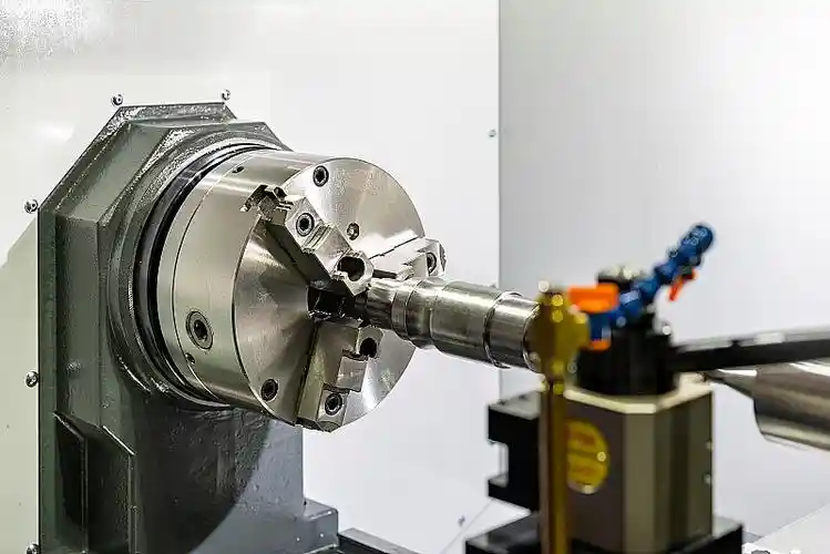
2. Clamping

Fixture stiffness must be sufficient. Finite element analysis suggests deformation <0.01 mm/1000 N ensures stable processing.
For hydraulic chucks:
Steel: 80–120 kN
Aluminum: 40–60 kN
This secures the part without deforming it.
When using dual tailstock, align concentricity to within 0.01 mm/m—otherwise, workpiece wobble will ruin efficiency.
VII. Conclusion
Improving CNC lathe cutting and grooving efficiency requires comprehensive optimization of tools, parameters, programming, machine status, workpiece, and clamping. Finding the right approach for your production line is key.
Minnuo offers technical support across all these areas and can help boost your efficiency.
If you're exploring ways to improve your CNC machining productivity or looking for a reliable CNC lathe, feel free to contact us. Minnuo is ready to provide professional solutions and support.


 Email
Email sales1: +86 13295238763

