



Interpretation of Core Parameters for Turn-Mill Machining Centers: How to Understand Spindle Speed, Travel, and Tool Magazine Capacity?
When purchasing or commissioning a turn-mill machining center, many engineers and purchasers often feel overwhelmed by the dense parameter tables. Questions like "What's the difference between a spindle speed of 3000rpm and 6000rpm?" "How to match travel parameters with my part dimensions?" and "Is a larger tool magazine capacity always better?" are common. In fact, the three core parameters—spindle speed, travel, and tool magazine capacity—directly determine the machining capability, efficiency, and application scenarios of the equipment. This article will break down these key indicators in plain language, helping you quickly determine whether the equipment meets your production needs and avoid wasting money on unsuitable machines.
I. First, Understand the Logic: Why Are Core Parameters the "Three Pillars"?
The core value of a turn-mill machining center lies in "completing multi-process machining with a single clamping". Spindle speed, travel, and tool magazine capacity correspond exactly to the three core requirements: "machining precision and efficiency", "machining range", and "continuous machining capability". Whether it is mass production of auto parts or customized machining of precision parts for aerospace, the matching degree of these three parameters directly affects the production cycle, product qualification rate, and overall production cost.
For example, when machining an aluminum alloy part with a diameter of 50mm, a machine with a spindle speed of 3000rpm may require multiple passes, while one with 6000rpm can achieve high-speed cutting, increasing efficiency by more than 40%. However, if machining a cast iron part with a diameter of 200mm, excessively high speed will instead accelerate tool wear—at this point, spindle rigidity is more important than speed. This is the core meaning of parameter matching: there are no "best" parameters, only "most suitable" ones.
II. Spindle Speed: It's Not Just About Numbers, but "Compatibility"
The spindle is the "power core" of a turn-mill machining center, and its speed directly determines the tool cutting speed and machining surface quality. However, when faced with a speed range like "1000-8000rpm" on the parameter table, many people fall into the misunderstanding that "higher speed is better". In fact, interpreting spindle speed requires a comprehensive judgment based on machining materials, part precision, and tool type.
2.1 Core Indicators: Rated Speed vs. Maximum Speed—Don't Confuse Them
Parameter tables usually mark two values: "maximum speed" and "rated speed". The former is the maximum speed the equipment can reach for a short time, while the latter is the speed at which it can operate stably for a long time. When purchasing, focus on the rated speed. For example, if a machine is marked with "maximum speed 8000rpm, rated speed 6000rpm", it means it can operate at 6000rpm for a long time and occasionally reach 8000rpm. Long-term operation at the maximum speed will significantly shorten the spindle life.
2.2 Matching Formula: The Golden Rule for Speed, Material, and Part Size
Different materials require different cutting speeds, and the spindle speed must match this. Reference formula: Spindle Speed (rpm) = Cutting Speed (m/min) × 1000 ÷ (π × Part Diameter (mm)). Here are some common scenarios:
- Aluminum Alloy/Copper Alloy (Easily Machinable Materials): The cutting speed is usually 150-300m/min. For a part with a diameter of 100mm, the required speed is 477-955rpm; for a small part with a diameter of 10mm, the speed needs to be 4774-9549rpm. In this case, a high-speed spindle (e.g., 6000-10000rpm) is necessary.
- Carbon Steel/Alloy Steel (Medium-Hard Materials): The cutting speed is 80-150m/min. For a part with a diameter of 50mm, the required speed is 509-955rpm, which can be met by an ordinary spindle (1000-3000rpm).
- Cast Iron/Stainless Steel (Difficult-to-Machine Materials): The cutting speed is 30-80m/min. For a part with a diameter of 200mm, the speed only needs to be 48-127rpm. At this point, spindle rigidity is more important than high speed.
2.3 Hidden Detail: The Link Between Spindle Power and Speed
Speed is not an isolated indicator; it must be judged in conjunction with spindle power. For example, two machines both marked with "rated speed 6000rpm" may have powers of 15kW and 22kW respectively. The latter has stronger cutting force at high speeds and can handle harder materials or deeper cutting depths. If your machining requirement is "high-speed cutting + large feed rate", be sure to choose a combination of "high speed + high power".
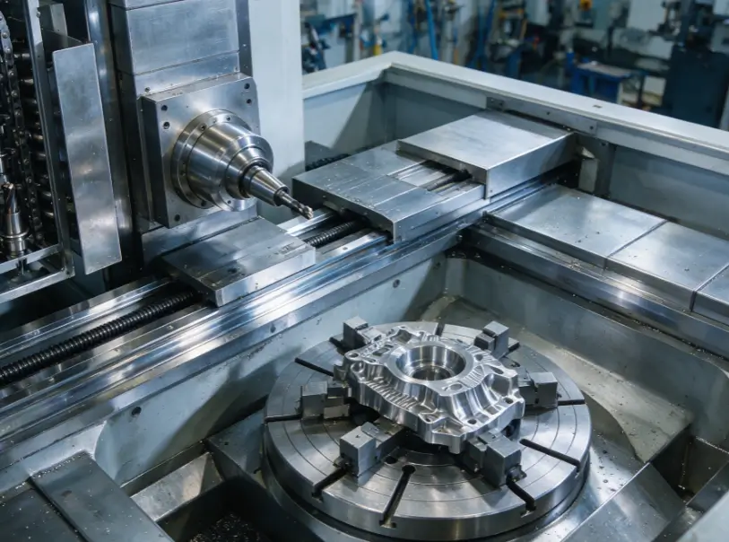
III. Travel Parameters: The "Hard Limit" of Machining Range—10mm Makes a Difference
Travel parameters define the "machining space" of a turn-mill machining center. Simply put, they refer to "the maximum distance the spindle and worktable can move", which directly determines the maximum size of parts the equipment can machine. The travel of turn-mill equipment is usually divided into "turning travel" and "milling travel", and neither should be ignored.
3.1 Key Travel Indicators: These Numbers Must Be Remembered
Parameter labeling varies slightly among different manufacturers, but the core indicators are consistent. Focus on verifying the following items when purchasing:
| Parameter Type | Core Meaning | Application Scenario Reference |
| Maximum Turning Diameter | The maximum distance from the spindle center to the turret, determining the maximum outer diameter of the part | To machine a flange with φ300mm, choose a machine with ≥300mm |
| Maximum Turning Length | The maximum distance from the spindle chuck to the tailstock center, determining the maximum length of the part | To machine a shaft part of 500mm in length, choose a machine with ≥500mm |
| X/Z Axis Travel (Milling) | The movement range of the milling spindle in X/Z directions, determining the milling range | To mill a 100×200mm plane, X-axis ≥100mm and Z-axis ≥200mm are required |
| Y Axis Travel (If Available) | The movement distance of the milling spindle in the Y direction, used for side milling | To machine a side groove on a part, the Y-axis travel must cover the groove depth |
3.2 Pitfall Warning: Reserve "Safety Margin"—Don't Buy Exactly at the Upper Limit
Many people choose equipment directly based on the "maximum part size". For example, when machining a φ250mm part, they buy a machine with a maximum turning diameter of 250mm—this is a typical mistake. After clamping, the part will occupy space due to the chuck, and the tool needs to reserve a retraction distance during machining. It is recommended to select the travel according to the standard of "maximum part size + 5%-10%". For example, a φ250mm part requires a machine with a maximum turning diameter of ≥275mm to avoid the problem of "being able to clamp but unable to complete machining".
3.3 Special Scenario: Pay Attention to "Travel Linkage" for Irregular Parts
When machining irregular parts (such as bent pipes and complex curved parts), it is necessary to consider not only the travel of a single axis but also the effective travel during multi-axis linkage. For example, in a 5-axis turn-mill machining center, the actual available travel of the X/Z axes will decrease when the A/C axes rotate. Before purchasing, it is best to ask the manufacturer for a "linkage travel simulation diagram" to ensure the equipment can cover all machining surfaces of the part.
IV. Tool Magazine Capacity: Not the Larger the Better—Depends on "Tool Change Frequency" and "Number of Processes"
The tool magazine is the key to realizing "continuous multi-process machining" in a turn-mill machining center, with capacities ranging from 6 to 60 tools. Many purchasers believe that "a larger tool magazine makes machining more convenient", but in reality, an excessively large tool magazine increases equipment cost and tool change time, while a too-small one requires frequent manual tool changes, affecting efficiency. The core of judging tool magazine capacity lies in the "number of tools required for a single machining process" and "production batch".
4.1 Tool Magazine Capacity Selection: Match According to "Process Complexity"
Different machining requirements have vastly different demands on tool magazine capacity. Refer to the following scenarios:
- Simple Process Machining (e.g., External Turning + Drilling): Only 3-5 tools are needed (external turning tool, drill bit, chamfering tool, etc.). A tool magazine with 6-12 tools is sufficient, offering the best cost-effectiveness. For example, in mass production of auto half-shafts with fixed processes, a small-capacity tool magazine meets the needs.
- Medium-Complexity Machining (Turn-Mill Combination + Tapping): 8-15 tools are required, such as turning tools, milling cutters, taps, and slotting cutters. A tool magazine with 16-24 tools is recommended to avoid frequent tool changes. For example, machining a gear shaft of a gearbox requires turning, keyway milling, and tapping processes, and a 20-tool magazine enables continuous machining.
- High-Complexity Machining (Irregular Parts + Multi-Surface Milling): For parts like aerospace engine blades, more than 20 tools are needed, including rough milling cutters, finish milling cutters, ball-end mills, and thread tools. In this case, a tool magazine with more than 30 tools is required, and a chain-type tool magazine may even be equipped to increase capacity.
4.2 Hidden Indicator: Tool Change Speed Affects Efficiency More Than Capacity
In addition to capacity, the "tool change time" of the tool magazine (the time from tool unclamping to clamping completion) is also crucial. For example, between two machines with 24-tool magazines, one with a tool change time of 1.5 seconds and the other 3 seconds, the number of parts processed per hour will differ by 10%-15% in mass production. If your production is "large-batch and fast-paced", prioritize equipment with a tool change time ≤2 seconds instead of blindly pursuing large capacity.
4.3 Practical Suggestion: Choose "Expandable Tool Magazine" for Small-Batch and Multi-Variety Production
If your enterprise produces a variety of parts with small batches and the tool requirements vary greatly for each machining task, it is recommended to choose equipment with an "expandable tool magazine"—a basic capacity of 20 tools that can be increased to 40 as needed. This not only meets current needs but also reserves space for future capacity upgrades, avoiding equipment idleness and waste.
V. Ultimate Decision: The "Coordinated Matching" Formula for the Three Core Parameters
After understanding the interpretation of individual parameters, you may wonder: "How to balance if my needs include both simple and complex parts?" The answer is to "focus on core needs while considering compatibility". Follow these steps to make a decision:
- Define Core Scenarios: List the main machining parts (size, material, process) for the next 3 years, and select parameters based on the needs of these parts instead of accommodating "occasional complex machining" (which can be solved by outsourcing or equipment rental).
- Calculate Total Cost: For example, when machining an aluminum alloy part with φ100mm, a high-speed spindle (6000rpm) can process 10 more parts per hour than an ordinary spindle (3000rpm). Calculated at a profit of $50 per part, this generates an additional $100,000 in revenue per year (2000 working hours), which is enough to cover the price difference of the spindle.
- Reserve Upgrade Space: Reserve a 10% margin for travel, choose an expandable tool magazine, and select a spindle power that is 20% higher than the current demand to avoid equipment obsolescence due to capacity upgrades within 1-2 years of use.
VI. Summary of Common Misunderstandings: Avoid These Mistakes
- Misunderstanding 1: Focusing only on maximum speed while ignoring rated speed—leading to long-term overloaded operation of the equipment and shortened service life.
- Misunderstanding 2: Buying travel that exactly matches the part size—failing to reserve space for clamping and tool retraction, making complete machining impossible.
- Misunderstanding 3: Blindly pursuing a large tool magazine—increasing equipment costs and slowing down tool change speed, which instead reduces efficiency.
- Misunderstanding 4: Ignoring parameter linkage—for example, a high-speed spindle matched with a low-power motor cannot achieve high-speed cutting.
Interpreting the parameters of a turn-mill machining center is essentially the "art of matching production needs with equipment capabilities". Spindle speed determines the "upper limit of machining efficiency", travel defines the "boundary of machining range", and tool magazine capacity decides the "continuous machining capability". As long as you grasp these three cores and combine them with your own part size, material, and process requirements, you can accurately select the "most cost-effective" equipment, converting every investment into improved production efficiency. If you have special machining scenarios, feel free to leave a message sharing your specific needs, and we will provide you with customized parameter matching suggestions.
 Email
Email sales1: +86 15312799623