Reasons and Solutions for Tool Changer Jamming in Gantry and Vertical Machining Centers
In the manufacturing industry, gantry machining centers and vertical machining centers are the main equipment for precision production, with the tool changers being crucial components that ensure their efficient operation. However, tool changer jamming remains a persistent issue that disrupts production schedules, increases downtime, and can even cause damage to the tools or equipment.
In fact, tool changer jamming in machining centers is rarely caused by a single "sudden" issue. It is more often the result of multiple factors working together, such as long-term wear of mechanical components, neglect of tool management, occasional control system failures, or lapses in operational details.
Next, we will analyze the root causes of tool changer jamming and provide practical solutions.
I. Root Causes of Tool Changer Jamming in Machining Centers
Tool changer jamming is rarely caused by a single factor; it typically results from a combination of mechanical wear, improper tool management, control system failures, or operational mistakes. A systematic breakdown of these causes is essential for effective troubleshooting.
(A) Mechanical Structure Issues
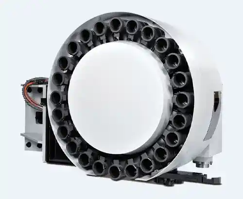
Mechanical components are the core framework of the tool changer. Long-term high-frequency operation without proper maintenance can lead to component wear and loosening, which is the most common cause of tool jamming.
Transmission Chain Slack or Wear: The transmission chain is responsible for the stable rotation of the tool changer. Lack of maintenance over time can result in wear of the chain pins, deformation of rollers, and increased operational gaps. This can cause uneven motion (manifesting as "sticking"), and in severe cases, the tool changer may stall. Especially in gantry machining centers, where the tool changer load is heavier, insufficient chain tension may also lead to positioning shifts, causing tool misalignment and triggering tool jamming during tool changes.

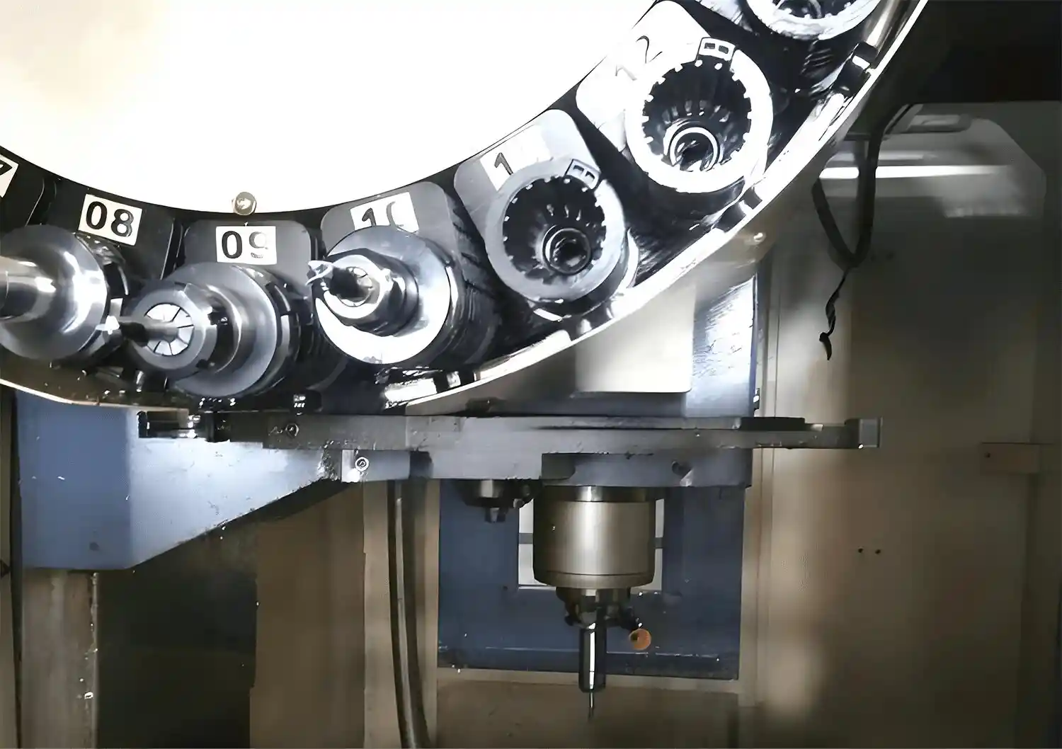
Wear of Positioning Pins: Positioning pins are key components that ensure precise tool placement. With repeated use, the top of the positioning pins may wear down and become rounded, causing a reduction in positioning accuracy from 0.01mm to over 0.1mm. This causes the tool to shake within its position, which, during tool changes, could lead to collisions with the internal walls of the tool changer or cause a complete jam.
Deformation of the Tool Changer Frame: Long-term overloading or external impacts may cause the tool changer frame to deform. This deformation can lead to interference between internal components, such as misaligned guide rails or tool position offsets, ultimately preventing smooth tool entry or exit from the tool changer.
(B) Tool-Related Issues
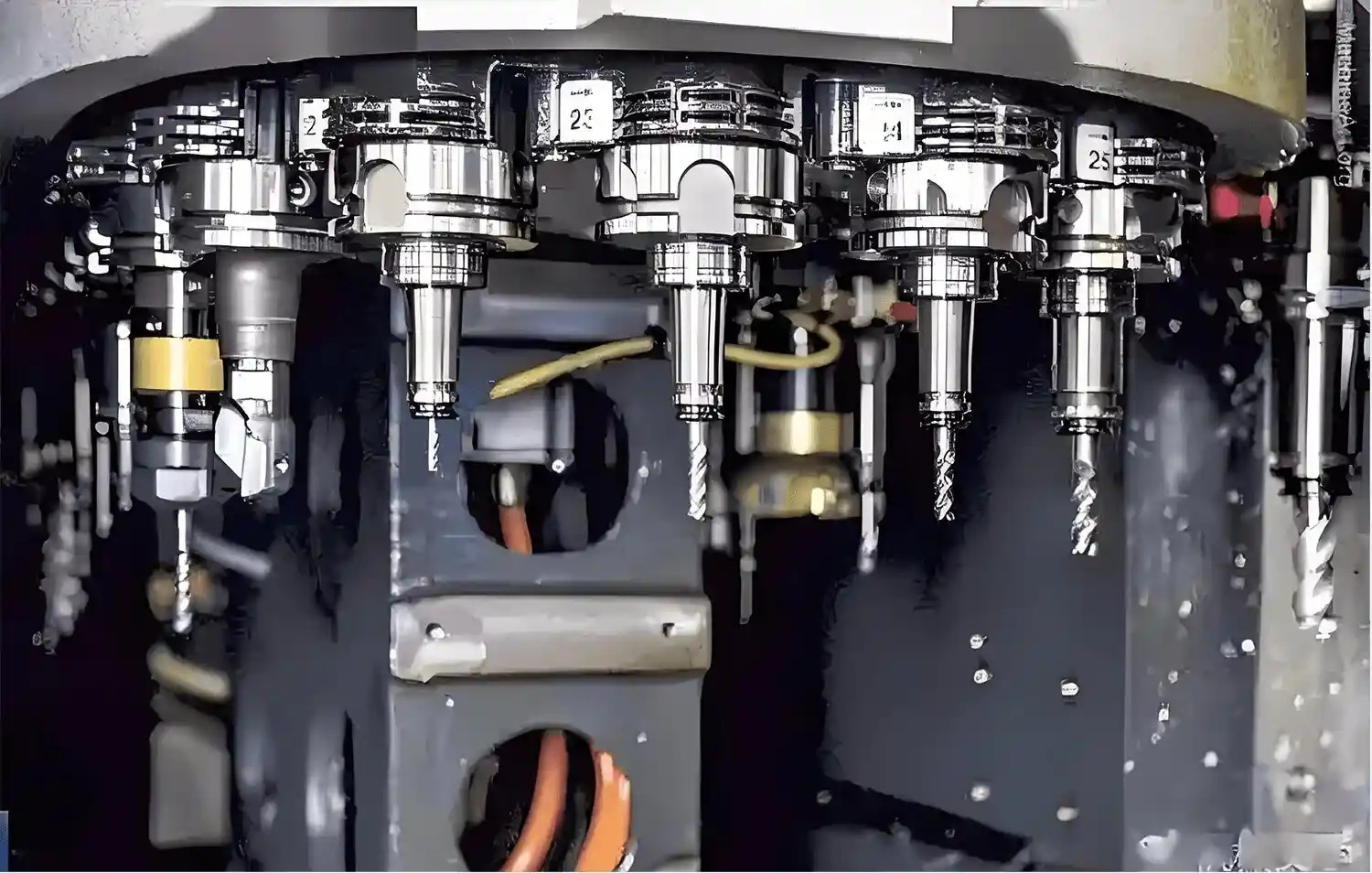
The tools and their accessories are in direct contact with the tool changer, and poor tool management is a common factor contributing to tool jamming.
Loose Tool Clamping: Worn or improperly adjusted clamping mechanisms (such as collets or clamps) can cause tools to be held insecurely. During rotation, the tool's center of gravity may shift, leading to collisions with the tool changer structure.
Damage to Tool Holders: Tool holders may suffer cracks, dents, or warping due to improper storage or accidental impacts, causing irregular shapes. These irregularities can cause the tool to get stuck in the tool changer during insertion or extraction.
Mismatched Tool Sizes: Tools that exceed the design specifications of the tool changer in terms of length or diameter can disrupt smooth operation. Tools that are too long may collide with the top of the tool changer or adjacent tools, while overly thick tools may get stuck in their designated positions.
(C) Control System Failures
Modern tool changers rely on precise electronic control, and any system failures can disrupt the coordination between mechanical motion and operational logic.
Program Errors: Errors in tool change instructions, incorrect tool number assignments, or timing mismatches in the control program can lead to abnormal actions by the tool changer. For example, if the program instructs the tool changer to rotate to tool position 15 but the tool has not yet detached from position 10, this situation will inevitably cause tool jamming.
Sensor Failures: Position sensors and tool detection sensors provide real-time feedback for precise control. Dirt accumulation, wiring issues, or component aging can lead to erroneous sensor signals (such as falsely reporting "tool in position"), causing motion misalignment and tool jamming.
(D) Operational Mistakes
Human factors also play an important role. Improper setup or handling during operation can introduce avoidable tool jamming risks.
Incorrect Tool Installation: If the tool is not fully inserted into the tool holder, or if the clamping bolts are over-tightened (causing tool holder deformation), or the tool is installed with a misaligned axis, it may lead to instability. This instability becomes apparent during the rotation or removal of the tool from the tool changer, resulting in jamming.
Improper Tool Change Process: Skipping the pre-check process (such as failing to clean debris from tool positions) or manually interrupting an automatic tool change cycle can disrupt the tool changer’s operating sequence, leading to positioning errors and tool jamming.
II. Step-by-Step Troubleshooting and Solutions for Tool Changer Jamming
When a tool changer jam occurs in a machining center, a systematic approach can ensure the safe and efficient resolution of the issue, minimizing production downtime to the greatest extent.
(A) Initial Check and Assessment
Emergency Stop and Safety Check: Immediately stop the machine to prevent further damage. Visually inspect the jammed tool area to check for obvious problems (such as misaligned tools, debris in the tool changer, or visible mechanical damage).
Control System Verification: Use the CNC system to check error logs and active alarm messages (such as "tool not in position" or "axis overload"). Confirm that the tool change program follows the expected sequence and that the tool numbers are assigned correctly.
(B) Mechanical and Tool Inspection
Transmission Chain and Positioning Pin Check:
Inspect the transmission chain for wear, elongation, or loose links. Use a tension meter to measure chain tension (refer to the manufacturer’s recommended optimal values). Replace worn-out chains and adjust the tensioner as needed.
Inspect the positioning pins for wear or deformation. Use a micrometer to measure the pin diameter, and if the wear exceeds 0.05mm, replace the positioning pins to restore positioning accuracy.
Tool and Tool Holder Verification:
Use a torque wrench to check the tool clamping force, ensuring it meets the manufacturer’s requirements (standard tool holders usually require 35-50 Nm). Replace worn clamping components (such as collets or springs).
Visually inspect and use a straightness gauge to check for damage to tool holders. Discard any holders with cracks or warping.
Frame and Alignment Check:
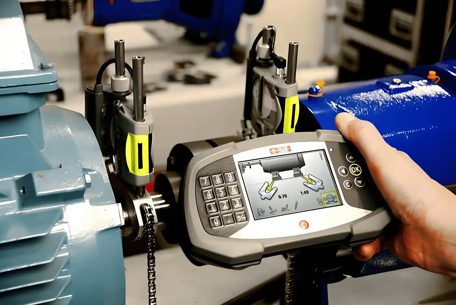
Use a laser alignment tool to check if the frame has deformed, particularly the parallelism between the guide rails and the tool changer’s rotating axis. Minor deformation can be corrected by adjusting mounting bolts; severely deformed frames should be replaced to avoid recurring issues.
(C) System Repair and Recovery
Sensor and Solenoid Valve Maintenance:
Clean sensor lenses with a lint-free cloth and check wiring connections. Use diagnostic software to test sensor functionality. Faulty sensors (such as photoelectric or proximity sensors) should be replaced if calibration fails.
Inspect solenoid valves for blockages or leaks. Use compressed air to clean valve ports and replace worn seals to ensure smooth pneumatic/hydraulic control of the tool changer’s movement.
Program and Parameter Adjustments:
A professional technician should adjust the PLC program to correct timing errors or logical flaws in the tool change sequence.
If key parameters (such as tool change speed or acceleration) have been altered, reset them to the manufacturer’s recommended values.
(D) Post-Recovery Testing
After resolving the issue, perform an empty run of the tool change cycle (without a workpiece) to verify smooth operation. Monitor for unusual noises, vibrations, or error messages. Perform 5-10 consecutive tool changes to ensure stability before resuming production.
III. Preventive Measures to Avoid Recurrence of Tool Jamming
Proactive maintenance is key to reducing tool jamming events:
Regular Mechanical Inspections: Inspect the transmission chain, positioning pins, and guide rails weekly. Lubricate moving parts with manufacturer-approved lubricants to reduce friction and wear.
Strict Tool Management: Establish a rigid inspection process for tools, ensuring tool holders are undamaged and tools meet tool changer specifications. Store tools in a clean, dry environment to prevent corrosion.
System Calibration: Calibrate sensors monthly and verify program logic to maintain control accuracy. Train operators to recognize early warning signs (such as abnormal noises during tool changes) and report issues promptly.
Conclusion
When a machining center tool changer malfunctions, we can follow the troubleshooting steps outlined above to conduct an initial repair. If the issue persists, it’s advisable to consult professionals. Feel free to contact Minnuo, as a machine tool manufacturer, for expert solutions. Remember, never disassemble the equipment yourself to avoid personal injury or damage.
 Email
Email sales1: +86 15312799623