



Deep-Hole Chip Evacuation on CNC Vertical Lathes: Causes and 5 Solutions
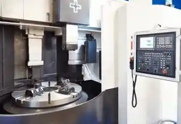
Poor chip evacuation is a common challenge during deep-hole machining on CNC vertical lathes. As hole depth increases, chips become more difficult to remove from the cutting area, potentially causing surface scratches, excessive cutting heat, accelerated tool wear, and unexpected machining interruptions.
The problem is particularly noticeable when machining deep internal bores or drilling holes with a high depth-to-diameter (L/D) ratio. Restricted chip flow, unsuitable cutting parameters, and insufficient coolant delivery can all contribute to chip accumulation.
Five practical methods can improve deep-hole chip evacuation on CNC vertical lathes: high-pressure coolant, through-tool coolant, vibration-assisted chip breaking, compressed air or minimum quantity lubrication (MQL), and cutting tool geometry optimization.
However, the best solution depends on the machining operation, workpiece material, hole dimensions, chip characteristics, and machine configuration.
This article explains the main causes of poor chip evacuation, compares five technical solutions, and provides practical recommendations for selecting the right approach.
Note: The methods discussed apply to compatible deep-hole drilling and internal boring operations on CNC vertical lathes. Specialized drilling processes may require dedicated tooling, coolant systems, or machine capabilities.
I. Causes of Poor Chip Evacuation in Deep-Hole Machining
Efficient chip removal depends on chip formation, cutting conditions, coolant delivery, and the available evacuation path.
The following factors are common causes of chip accumulation during deep-hole machining.
1. Long or Continuous Chip Formation
During machining, certain materials, such as stainless steel and other ductile alloys, may produce long, continuous chips.
If these chips are not properly broken, they can become tangled around the cutting tool or accumulate inside the bore.
This increases friction and may damage the machined surface or cutting edge.
Key factors: Workpiece material, feed rate, cutting speed, and chip-breaker geometry.
2. Insufficient Coolant Pressure or Flow
Coolant plays an important role in removing cutting heat, reducing friction, and transporting chips away from the cutting zone.
If coolant pressure or flow is inadequate, chips may remain inside the hole instead of being flushed out.
Blocked coolant passages, insufficient pump capacity, unsuitable nozzle direction, and poor filtration can further reduce evacuation efficiency.
Key factors: Coolant flow rate, pressure, delivery direction, and return path.
3. Restricted Chip Evacuation Space
As the depth-to-diameter ratio increases, chips must travel a longer distance through a confined space.
In deep-hole drilling, inadequate flute capacity or blocked evacuation passages can lead to chip packing.
During deep internal boring, insufficient clearance between the boring bar and bore wall can also obstruct chip removal.
The orientation of the hole and whether it is blind or through can further influence chip accumulation.
Key factors: Hole depth, diameter, tool geometry, available clearance, and chip exit path.
4. Unsuitable Tool Geometry and Cutting Parameters
Incorrect tool geometry or cutting conditions can produce chips that are difficult to break and evacuate.
For example, an unsuitable feed rate may generate long ribbon-shaped chips, while excessive tool overhang can increase vibration and reduce cutting stability.
Worn cutting edges and inappropriate chip-breaker designs can make the problem worse.
Key factors: Cutting tool selection, chip-breaker design, tool overhang, feed rate, and cutting speed.
Before changing the machining process, operators should identify whether the main problem is excessive chip length, inadequate coolant delivery, or restricted chip flow.
II. Five Solutions to Improve Deep-Hole Chip Evacuation
The following five methods address different aspects of chip formation and removal.
They are not necessarily alternatives to one another. In many applications, combining appropriate coolant delivery with optimized tool geometry provides better results than relying on a single method.
1. High-Pressure Coolant Systems (HPC)
Working Principle
High-pressure coolant systems deliver cutting fluid toward the machining zone to assist chip evacuation, cooling, and lubrication.
In compatible deep-hole operations, a properly designed coolant system helps transport chips away from the cutting edge and through the available evacuation path.
Advantages
- Improves chip flushing in suitable drilling and boring applications.
- Helps reduce cutting heat and friction.
- Supports more consistent cutting conditions.
- Can reduce chip accumulation when combined with suitable tooling.
Limitations
- May require an upgraded pump, filtration system, and coolant circuit.
- Higher pressure alone cannot compensate for insufficient flow or a blocked chip path.
- Operating pressure must remain within machine and tool specifications.
- Additional coolant management and mist control may be necessary.
Applicable Scenarios
Deep-hole drilling, internal boring, and demanding machining operations where coolant-assisted chip evacuation is required.
For materials that produce difficult-to-control chips, correctly directed coolant can improve process stability.
Selection Tip: Check both coolant pressure and flow rate. Increasing pressure without confirming adequate flow and chip clearance may not solve the problem.
2. Through-Tool Coolant Technology
Working Principle
Through-tool coolant systems deliver cutting fluid directly to the cutting zone through internal passages in the drilling tool, boring bar, or tool holder.
Compared with external coolant delivery, internal channels can improve access to cutting areas that are difficult to reach in deep holes.
Advantages
- Delivers coolant closer to the cutting edge.
- Improves cooling and lubrication inside confined bores.
- Supports chip transport through the intended evacuation path.
- Can work together with high-pressure coolant systems.
Limitations
- Requires compatible tooling and coolant connections.
- Internal passages may become blocked by contamination.
- Coolant delivery capability depends on the tool and machine configuration.
- Special deep-hole tooling may require additional accessories or dedicated equipment.
Applicable Scenarios
Deep-hole drilling and internal boring applications using tools designed for internal coolant supply.
For example, certain deep-hole drilling systems use internal coolant delivery with external chip evacuation, while other dedicated systems use external coolant supply and internal chip removal.
The correct method depends on the drilling system.
Selection Tip: High-pressure coolant and through-tool coolant are complementary technologies. The first describes coolant supply conditions, while the second describes the delivery route.
3. Vibration-Assisted Chip Breaking
Working Principle
Vibration-assisted machining introduces controlled oscillation into the cutting process.
In compatible vibration-assisted drilling systems, controlled axial movement can interrupt continuous chip formation and produce shorter chips that are easier to evacuate.
Advantages
- Helps break long or continuous chips.
- May reduce chip entanglement in suitable applications.
- Can improve chip transport when conventional cutting produces difficult chip shapes.
- Offers an additional process option for challenging materials.
Limitations
- Requires specialized equipment, tooling, or compatible motion control.
- Vibration settings must match the cutting conditions.
- Incorrect settings may increase cutting forces or affect hole quality.
- Not all CNC vertical lathes support vibration-assisted drilling.
Applicable Scenarios
Specialized drilling applications where conventional chip-breaking methods are insufficient and suitable vibration-assisted equipment is available.
Selection Tip: Consider vibration assistance only after evaluating tool geometry, cutting parameters, and coolant delivery. It should be validated through controlled machining tests rather than treated as a universal solution for precision machining.
4. Compressed Air-Assisted Chip Removal and MQL
Working Principle
Compressed air can help transport chips away from certain cutting zones. Minimum Quantity Lubrication (MQL) introduces a small amount of lubricant into an air stream to provide localized lubrication.
These methods may reduce the amount of liquid coolant used in compatible machining operations.
Advantages
- Can support chip removal in suitable dry or near-dry machining processes.
- Reduces reliance on conventional flood coolant when the process permits.
- May simplify coolant handling in selected applications.
- Can be integrated with compatible tool and machine configurations.
Limitations
- Air provides much less cooling capacity than conventional liquid coolant.
- Chip evacuation may be difficult in long, confined, or blind holes.
- High air consumption can increase operating costs.
- Requires suitable enclosure, chip containment, and mist or dust control.
- Not appropriate for every material or deep-hole machining process.
Applicable Scenarios
Selected drilling and boring operations where air-assisted evacuation or MQL has been validated for the material, hole geometry, and machine configuration.
Selection Tip: Do not automatically replace liquid coolant with compressed air in deep-hole machining. Verify whether the air system can remove chips effectively while maintaining adequate cooling and process safety.
5. Cutting Tool Geometry and Chip Control Optimization
Working Principle
Tool geometry influences how chips form, curl, break, and move away from the cutting zone.
Selecting the appropriate drill flute, insert chip breaker, cutting edge geometry, and tool clearance can improve chip evacuation without requiring major machine modifications.
Key Optimization Methods
Chip-Breaker Selection: Choose an insert geometry designed for the workpiece material and cutting parameters to promote manageable chip formation during internal boring.
Flute and Evacuation Path Design: For drilling, use tooling with suitable flute capacity and chip evacuation geometry for the required hole depth.
Tool Clearance: For internal boring, maintain sufficient clearance between the boring bar and bore wall for chip movement.
Cutting Parameter Optimization: Adjust feed rate and cutting speed within the tool manufacturer's recommended range to improve chip shape and cutting stability.
Advantages
- Directly addresses chip formation.
- Can be implemented through appropriate tool selection.
- Often complements existing coolant systems.
- May improve tool life and hole quality when properly applied.
Limitations
- Tool geometry must match the material and operation.
- A geometry effective in one cutting condition may not perform equally well in another.
- Excessive chip accumulation may still require improved coolant delivery.
- Tool wear and machining stability must be considered.
Applicable Scenarios
Deep-hole drilling and internal boring operations where long chips, poor chip breaking, or restricted chip flow are the primary problems.
Selection Tip: Optimize chip formation before investing in more complex evacuation equipment. Shorter, manageable chips are generally easier to transport through confined cutting areas.
III. Comparison of Five Deep-Hole Chip Evacuation Solutions
Each solution addresses a different aspect of chip control. The most effective option depends on whether the main problem is chip formation, coolant delivery, or the available evacuation path.
| Solution | Main Function | Suitable Conditions | Main Limitation |
|---|---|---|---|
| High-Pressure Coolant | Flush chips and manage cutting heat | Compatible deep-hole drilling and boring | Requires adequate pressure, flow, and filtration |
| Through-Tool Coolant | Deliver coolant directly to the cutting zone | Tools with internal coolant passages | Requires compatible tools and coolant connections |
| Vibration-Assisted Chip Breaking | Interrupt continuous chip formation | Specialized, validated drilling applications | Requires compatible equipment and process control |
| Compressed Air / MQL | Assist chip transport with limited liquid coolant | Selected dry or near-dry operations | Limited cooling and deep-hole flushing capability |
| Tool Geometry Optimization | Improve chip breaking and chip flow | Material-specific drilling and boring | Requires appropriate tool selection and cutting parameters |
Which Solution Should Be Considered First?
For many CNC vertical lathe applications, tool geometry and cutting parameter optimization are practical starting points, followed by verification of coolant flow, pressure, and delivery.
If chips continue to accumulate, through-tool coolant or a compatible high-pressure system may be necessary.
Vibration-assisted machining and compressed air or MQL should be considered where their benefits are supported by the specific machining process.
There is no universal ranking of chip evacuation efficiency because performance varies with hole dimensions, materials, machine configuration, and cutting conditions.
IV. How to Choose the Right Chip Evacuation Solution for CNC Vertical Lathes
Selecting an effective solution requires understanding the actual machining problem rather than relying only on production volume or cost.
1. For Long or Continuous Chips
Recommended Approach: Optimize cutting tool geometry and cutting parameters.
Select appropriate chip-breaker inserts for internal boring or suitable drill geometry for deep-hole drilling.
Adjust cutting parameters according to the tool manufacturer's recommendations and verify the resulting chip shape.
If necessary, evaluate controlled vibration-assisted chip breaking where compatible equipment is available.
2. For Chips Accumulating Inside Deep Holes
Recommended Approach: Check coolant delivery and the chip evacuation path.
Verify whether the coolant reaches the cutting zone with sufficient flow.
For compatible operations, consider through-tool coolant or a high-pressure coolant system.
Also check for blocked passages, insufficient flute capacity, or inadequate clearance around the boring tool.
For very high L/D ratios, dedicated deep-hole drilling tooling or equipment may be required.
3. For High-Load or Difficult-to-Machine Materials
Recommended Approach: Combine suitable cutting tools with controlled coolant delivery.
Materials such as stainless steel and heat-resistant alloys may require careful control of chip formation, cutting temperature, and lubrication.
High-pressure or through-tool coolant can be beneficial when supported by the cutting tool and machine specifications.
Tool geometry and cutting parameters should also be optimized for the specific material.
4. For Applications with Limited Coolant Use
Recommended Approach: Evaluate compressed air or MQL only where the process permits.
These approaches may be useful in selected applications, but their suitability depends on the material, hole depth, chip shape, and cooling requirements.
Where chip accumulation or excessive cutting heat remains a problem, a conventional liquid coolant system may be more appropriate.
Practical Selection Checklist
Before selecting a chip evacuation method, confirm:
- Machining operation: Deep-hole drilling or internal boring
- Hole geometry: Diameter, depth, L/D ratio, blind or through hole
- Workpiece material: Chip formation and cutting characteristics
- Tooling: Drill flute design, boring bar clearance, chip breakers
- Coolant system: Available pressure, flow, filtration, and delivery path
- Machine capability: Tool compatibility, available functions, and operating limits
These factors provide a more reliable basis for choosing an effective chip evacuation solution than production volume alone.
Conclusion
Poor chip evacuation during deep-hole machining on CNC vertical lathes can reduce machining stability, damage bore surfaces, accelerate tool wear, and interrupt production.
The main causes include continuous chip formation, insufficient coolant delivery, restricted evacuation space, and unsuitable tool geometry or cutting parameters.
The most effective approach is to identify the root cause first, then select the appropriate combination of chip control and evacuation technologies.
High-pressure coolant and through-tool coolant can improve chip flushing in compatible operations. Tool geometry optimization addresses chip formation, while vibration assistance and compressed air or MQL provide additional options for specific applications.
For manufacturers performing deep-hole drilling or internal boring, choosing the right method requires evaluating the material, hole dimensions, machine capability, and cutting conditions.
For assistance selecting a CNC vertical lathe or discussing machining requirements, visit MINNUO to explore suitable equipment configurations.
Frequently Asked Questions (FAQ)
Q1. What causes poor chip evacuation in deep-hole machining?
A:Poor chip evacuation is commonly caused by long or continuous chips, insufficient coolant flow, restricted evacuation space, unsuitable cutting parameters, or incorrect tool geometry. High depth-to-diameter ratios make chip removal more challenging.
Q2. How can I improve chip evacuation during deep-hole drilling on a CNC vertical lathe?
A:Start by checking chip formation, tool geometry, and cutting parameters. Verify coolant pressure, flow rate, and delivery. Through-tool coolant or high-pressure coolant may improve chip removal when compatible with the machine and tooling.
Q3. Is high-pressure coolant better than through-tool coolant?
A:They serve different functions. High-pressure coolant provides the pressure required for suitable fluid delivery, while through-tool coolant directs fluid through internal tool passages. The two technologies can be used together for effective chip evacuation.
Q4. Can compressed air replace coolant in deep-hole machining?
A:Not always. Compressed air can assist chip removal in selected applications, but it provides less cooling and may be insufficient for deep or confined holes. Its suitability depends on the workpiece material, hole geometry, tool design, and operating conditions.
Q5. Which chip evacuation method is best for CNC vertical lathes?
A:There is no single best method. Tool geometry optimization, through-tool coolant, and appropriately designed coolant systems are common approaches. The selection should be based on the actual chip problem, machining operation, hole dimensions, material, and available machine capabilities.
 Email
 sales1: +86 15312799623