



Slant Bed Lathe vs Flat Bed Lathe: Key Differences, Applications and Buying Guide
The short answer: neither a slant bed lathe nor a flat bed lathe is universally better. Slant bed turning centers are generally better suited to small-to-medium workpieces, repetitive production, and automation. Heavy-duty flat bed lathes are usually better suited to long shafts, large or heavy workpieces, repair machining, and applications requiring robust tailstock and steady-rest support. For large-diameter, short, heavy flanges and valve bodies, a vertical turning lathe should also be considered.
Quick Answer: Slant Bed or Flat Bed Lathe?
| Machine Type | Best Suited For |
|---|---|
| Slant bed lathe | Small-to-medium parts, higher production volumes, automatic turrets, bar feeding, robotic loading |
| Heavy-duty flat bed lathe | Long shafts, heavy workpieces, repair machining, steady-rest support, high part variety |
| Vertical turning lathe / VTL | Large-diameter, short, heavy flanges, rings, and valve bodies |
If your main goal is to reduce cycle time in repetitive production, start by evaluating a slant bed turning center. If the main challenge is workpiece length, weight, or support, evaluate a heavy-duty flat bed lathe first.
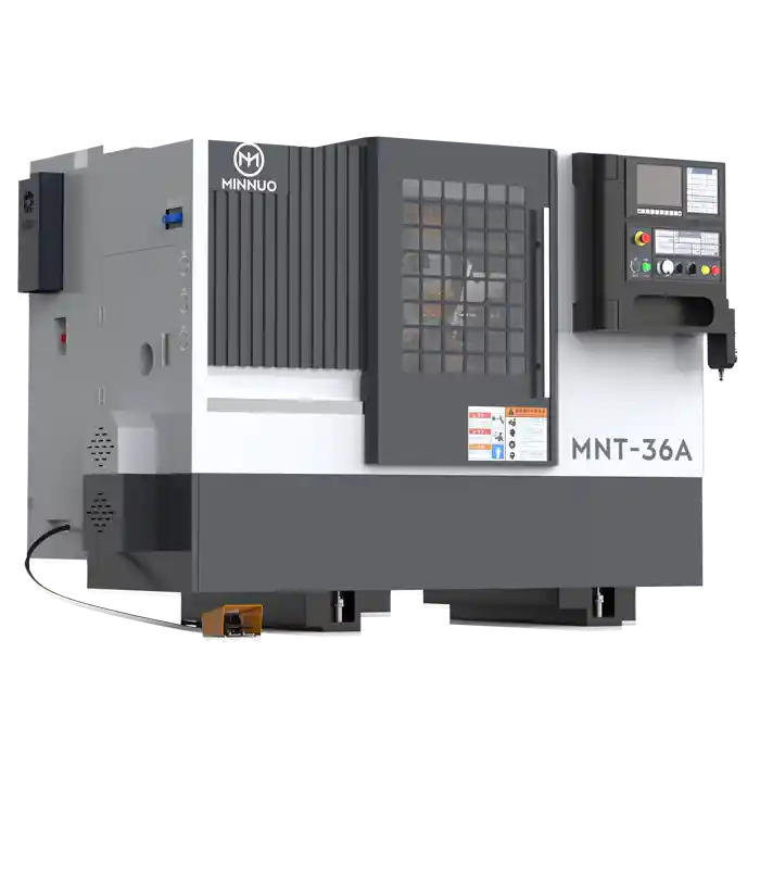
Slant Bed vs Flat Bed Lathe: What Is the Real Difference?
The real difference is not simply that one bed is inclined and the other is horizontal. The two machine architectures are typically optimized around different production requirements.
Modern slant bed turning centers commonly emphasize:
- compact machining zones;
- automatic turrets;
- higher rapid traverse rates;
- hydraulic chucks;
- bar feeders;
- parts catchers;
- C-axis capability;
- Y-axis capability;
- live tooling;
- robotic loading and unloading;
- repetitive production.
Heavy-duty flat bed CNC lathes typically emphasize:
- larger machine beds;
- longer distance between centers;
- larger spindle bores;
- robust tailstocks;
- steady rests;
- long-shaft machining;
- heavy workpiece capacity;
- flexible repair and low-volume machining.
The correct buying question is therefore not:
“Is a slant bed lathe more advanced than a flat bed lathe?”
It is:
“Which machine architecture better matches my workpiece envelope, material, weight, annual volume, and machining process?”
For materials such as 316L stainless steel and duplex stainless steel, machine selection must also account for relatively high cutting forces and cutting temperatures.
Sandvik Coromant specifically identifies high cutting forces, high temperatures, and plastic deformation as important challenges in austenitic and duplex stainless steel turning. See the Sandvik Coromant technical material on stainless steel turning.
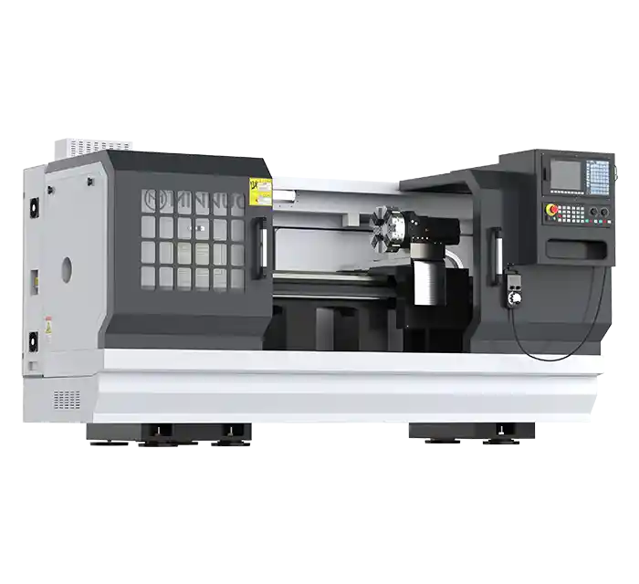
Slant Bed Lathe vs Flat Bed Lathe Specifications Compared
Before comparing machine specifications, one definition must be clear:
Maximum Turning Diameter and Swing Over Bed are not the same specification.
The three machines below are used to illustrate different machine architectures. They are not direct competitors in the same machine class.
| Specification | Haas ST-20 | DN Solutions PUMA 2100LY II | CNC-TAKANG LC30 |
|---|---|---|---|
| Machine type | Slant-bed turning center | Y-axis turning center | Heavy-duty flat-bed CNC lathe |
| Typical application | Small-to-medium batch parts | Complex precision batch production | Long shafts and heavy workpieces |
| Maximum turning diameter | 298 mm with BMT65; 300 mm with VDI; up to 330 mm with BOT configuration | 406 mm | Swing value should not be used as turning diameter |
| Maximum workpiece / bed swing | Maximum workpiece swing up to 533 mm | Evaluate separately from turning diameter | 770 mm swing over bed |
| Maximum turning length / distance between centers | 572 mm | 760 mm | 1,200–8,200 mm distance between centers |
| Maximum spindle speed | 4,000 rpm | 5,000 rpm | Approx. 300–800 rpm depending on spindle configuration |
| Maximum spindle power | 14.9 kW | 22 kW | Standard 18.5/22 kW, higher options available |
| Maximum spindle torque | 203 N·m at 500 rpm | 358 N·m | Depends on spindle and gearbox configuration |
| X/Z rapid traverse | 24/24 m/min | 30/30 m/min | Approx. 6 m/min |
| Long-shaft capability | Limited | Limited | Strong |
| Automation capability | Strong | Very strong | Usually not the primary design priority |
Current Haas ST-20 specifications show a maximum turning diameter of 298 mm with a BMT65 turret and 300 mm with a VDI turret. Haas comparison data also lists a 330 mm maximum turning diameter with a BOT configuration. Therefore, “330 mm maximum turning diameter” should not be presented as a universal ST-20 specification.
The published ST-20 specifications also include:
- maximum turning length: 572 mm;
- spindle speed: 4,000 rpm;
- spindle power: 14.9 kW;
- maximum spindle torque: 203 N·m at 500 rpm.
The DN Solutions PUMA 2100LY II published specifications include:
- maximum turning diameter: 406 mm;
- maximum turning length: 760 mm;
- spindle speed: 5,000 rpm;
- maximum power: 22 kW;
- maximum torque: 358 N·m;
- X/Z rapid traverse: 30/30 m/min.
The CNC-TAKANG LC30 represents a very different engineering approach. Its published specifications include:
- 770 mm swing over bed;
- 1,200–8,200 mm distance between centers;
- 560 mm bed width;
- 710 mm auxiliary guideway span;
- multiple low-speed spindle configurations.
Its design priorities are clearly focused on long workpieces and heavy-duty machining rather than high-speed production cycles.
Maximum Turning Diameter vs Swing Over Bed: What Is the Difference?
Maximum Turning Diameter refers to the practical diameter that can actually be machined under a defined machine and tooling configuration. Swing Over Bed describes the geometric diameter that can rotate above the machine bed without mechanical interference.
Therefore:
770 mm Swing Over Bed ≠ 770 mm Maximum Turning Diameter
Confusing these two values can significantly overestimate the practical machining capacity of a lathe.
For large-machine evaluation, check all of the following:
- swing over bed;
- swing over cross slide;
- maximum turning diameter;
- cross-slide geometry;
- turret or tool-post interference;
- chuck diameter;
- maximum workpiece weight.
When Is a Slant Bed Lathe the Better Choice?
A slant bed lathe is usually the better starting point when the workpieces are small to medium in size, production is repetitive, and cycle time or automation matters more than extreme workpiece length.
Typical parts include:
- valve stems;
- valve plugs;
- pipe fittings;
- small flanges;
- instrument fittings;
- pump sleeves;
- bearing sleeves;
- small and medium pump parts;
- bar-fed components.
These applications can take advantage of:
- hydraulic chucks;
- 8-, 12-, or higher-station turrets;
- bar feeders;
- automatic parts catchers;
- sub-spindles;
- live tooling;
- C-axis machining;
- Y-axis machining;
- robotic loading.
Machines such as the Haas ST-20 and PUMA 2100LY II, with rapid traverse speeds in the 24–30 m/min range, illustrate a design philosophy focused heavily on production efficiency.
Why Slant Bed Lathes Are Better Suited to Automation
Automated turning is more than simply adding a robot.
A complete automated process may include:
Automatic Loading → Chuck Clamping → Multi-Tool Machining → Inspection → Part Transfer → Automatic Unloading
Slant bed turning centers are commonly designed around this type of production flow.
For factories producing thousands or tens of thousands of repetitive parts per year, the better question is not:
“What is the largest diameter this machine can turn?”
It is:
“How many acceptable parts can this machine reliably produce per shift?”
Does a Slant Bed Lathe Really Improve Chip Evacuation?
Usually yes, but bed angle alone does not determine chip evacuation performance.
Actual chip evacuation also depends on:
- enclosure geometry;
- chip-chute angle;
- conveyor design;
- coolant flow;
- workpiece material;
- feed rate;
- chip-breaker geometry.
A more accurate engineering conclusion is:
Slant-bed architecture generally helps gravity move chips away from the turret and cutting zone, but actual chip evacuation performance depends on the complete cutting and chip-management system.
When Is a Flat Bed Lathe the Better Choice?
A heavy-duty flat bed lathe is usually more appropriate when workpieces become longer, heavier, larger, or when the workshop handles many low-volume repair jobs.
Typical applications include:
- 2,000–8,000 mm pump shafts;
- agitator shafts;
- large rolls;
- marine shafts;
- large pipe components;
- heavy cylindrical components;
- large repair parts.
At this point, machine selection shifts away from:
Automatic Turret + Rapid Traverse + Cycle Time
and toward:
Distance Between Centers + Tailstock + Steady Rest + Spindle Bore + Bed Span + Workpiece Weight + Low-Speed Torque
Published specifications for the CNC-TAKANG LC series illustrate this difference. LC30, LC35, and LC40 models provide swing-over-bed values of approximately 770 mm, 895 mm, and 1,020 mm respectively, with distance-between-centers options extending to approximately 8,200 mm.
So if the job is a 4,000 mm pump shaft:
whether the machine bed is inclined should not be the first buying criterion.
The first question should be:
Can the workpiece be properly supported while controlling deflection, vibration, and dimensional error during roughing and finishing
Flat Bed Lathe or Vertical Lathe: Which Is Better for Large Flanges?
For large-diameter, short, and heavy flanges, valve bodies, and ring-shaped parts, a vertical turning lathe may be more practical than a conventional horizontal flat bed lathe.
In a vertical machine:
the workpiece mass is primarily supported by the horizontal table.
On a horizontal lathe:
a significant portion of the workpiece load may act through the spindle, chuck, and support system.
This means the selection logic should not be reduced to:
Small Part = Slant Bed
Large Part = Flat Bed
A better starting point is:
| Workpiece Type | Machine Type to Evaluate First |
|---|---|
| Small-to-medium shaft parts | Slant bed turning center |
| Long shafts | Heavy-duty flat bed lathe |
| Large-diameter short flanges | VTL / vertical turning center |
| Large and heavy long parts | Heavy-duty flat bed lathe |
| Complex multi-face valve bodies | Turn-mill or machining center depending on process |
For vertical turning machine acceptance, ISO 13041-2:2020 provides specific geometric test guidance for numerically controlled turning machines with vertical workholding spindles.
Which Lathe Specifications Matter for Stainless Steel and Nickel-Alloy Machining?
For 316L, duplex, super duplex, and nickel-based corrosion-resistant alloys, maximum spindle power alone is not enough. Low-speed torque, machine rigidity, workholding, turret design, cooling, and chip control are often more important.
Buyers should examine:
- low-speed spindle torque;
- spindle power-torque curve;
- spindle bearing design;
- turret structure;
- toolholder size;
- bed and guideway span;
- chuck clamping capability;
- tailstock and steady-rest capability;
- high-pressure coolant options;
- thermal compensation strategy.
Sandvik Coromant notes that austenitic and duplex stainless steel turning involves high cutting forces and high cutting temperatures.
Spindle Power vs Torque: Which Matters More for Heavy Turning?
For large-diameter, low-speed rough turning, low-speed spindle torque is often more informative than a single maximum-kW figure.
Rotational mechanical power can be expressed as:
P = (2 × π × n × T) / 60000
Where:
- P = power, kW
- n = spindle speed, rpm
- T = torque, N·m
For example, if:
T = 203 N·m
and:
n = 500 rpm
then:
P = (2 × 3.1416 × 500 × 203) / 60000
P ≈ 10.63 kW
This explains why a spindle rated at a maximum of 14.9 kW does not necessarily produce 14.9 kW at 500 rpm.
Likewise, published maximum torque and maximum power values should not automatically be assumed to be simultaneously available across the full spindle-speed range.
Why You Should Request the Spindle Power-Torque Curve
Instead of asking only:
“How many kilowatts is the spindle?”
ask:
“Please provide the complete spindle power-torque curve, including continuous and short-time duty zones.”
The correct engineering sequence is:
Workpiece Diameter
↓
Recommended Cutting Speed
↓
Required Spindle Speed
↓
Available Continuous Torque at That Speed
This gives much more useful information than simply comparing:
15 kW vs 18.5 kW vs 22 kW
How Machine Rigidity Affects Duplex and Nickel-Alloy Turning
Difficult-to-machine materials expose weaknesses in the complete stiffness chain more quickly, and bed angle alone does not prove machine rigidity.
The stiffness chain includes:
Bed → Guideways → Spindle Bearings → Chuck → Workpiece → Toolholder → Turret
Weakness at any point can result in:
- chatter;
- dimensional variation;
- poor cylindricity;
- unstable surface finish;
- tool chipping;
- inconsistent tool life.
High cutting forces and cutting temperatures make this especially important in stainless steels and nickel-based alloys.
Therefore:
“A slant bed lathe is inherently more rigid than a flat bed lathe” is not a technically valid universal statement.
A large heavy-duty flat bed lathe can easily have greater static and dynamic cutting rigidity than a compact slant bed turning center.
How to Choose a Lathe for Long Shaft and Pump Shaft Machining
Long-shaft selection should begin with effective machining length, workpiece support, and deflection control—not bed angle.
Consider a 316L pump shaft:
- diameter: 80 mm
- length: 1,200 mm
Then:
L/D = 1200 / 80 = 15
How Does Length-to-Diameter Ratio Affect Shaft Turning?
As L/D increases, the risk of elastic deflection and vibration generally increases, but there is no universal L/D threshold that automatically determines when a steady rest is required.
The decision also depends on:
- depth of cut;
- cutting position;
- stock condition;
- material;
- unsupported length;
- chuck configuration;
- tailstock support;
- steady rest;
- follow rest;
- tolerance;
- surface-finish requirement.
For an:
Ø80 × 1,200 mm
pump shaft with:
L/D = 15
the process engineer should evaluate whether a:
steady rest
or:
follow rest
is required rather than assuming:
chuck + tailstock
is always sufficient.
Also note that the PUMA 2100LY II discussed earlier has a published maximum turning length of 760 mm, so it cannot machine the full 1,200 mm shaft in that example. A longer-bed configuration would be required.
Why Thermal Stability Matters More Than a Single Accuracy Claim
A statement such as “positioning accuracy ±0.005 mm” does not prove that the machine will maintain the same dimensional performance during hours of continuous production.
Before accepting an accuracy claim, ask:
- What was the test length?
- What was the ambient temperature?
- Was the machine warmed up?
- Was the spindle running?
- Were both positive and negative directions tested?
- How many positions were measured?
- How many repetitions were performed?
- What measuring instrument was used?
- Is the value positioning accuracy or finished-part accuracy?
For valve seats, mechanical sealing surfaces, pump-shaft bearing journals, and other precision features, the more important production question is often:
How much dimensional drift occurs as the machine reaches thermal equilibrium?
A serious FAT should therefore separate:
Cold-Machine Geometry
from:
Axis Positioning
and:
Warm-Machine Cutting Performance
Which ISO Standards Should Be Used for CNC Lathe Acceptance Testing?
A CNC lathe FAT should not simply state “according to ISO standards.” The applicable standard should be identified for each type of verification.
ISO 230-1: Geometric Accuracy Testing
ISO 230-1:2012 specifies methods for testing the geometric accuracy of machine tools operating under no-load or quasi-static conditions.
It provides an important general framework for machine-tool geometric verification.
ISO 230-2: Positioning Accuracy and Repeatability
ISO 230-2:2014 covers the determination of:
- positioning accuracy;
- positioning repeatability;
for numerically controlled linear and rotary axes.
It may be used for:
- type testing;
- acceptance testing;
- comparison testing;
- periodic verification;
- machine compensation verification.
Buyers can check the official ISO 230-2:2014 standard page to confirm the current standard status and scope.
The 2014 edition was reconfirmed in 2025 and remains current.
ISO 13041-1: Geometric Tests for CNC Turning Machines
ISO 13041-1:2020 is particularly relevant to this article because it applies specifically to:
numerically controlled turning machines and turning centers with horizontal workholding spindles.
It specifies geometric tests and corresponding tolerances and references ISO 230-1 methodology.
A practical acceptance framework is therefore:
ISO 230-1 → General geometric test methodology
ISO 230-2 → Axis positioning and repeatability
ISO 13041-1 → Geometric tests specific to horizontal-spindle CNC turning machines
CNC Lathe FAT Checklist: What Should Buyers Verify?
For machines used to produce critical valve, pump, shaft, or sealing components, the FAT should retain traceable data rather than simply record “passed.”
| FAT Item | Recommended Record |
|---|---|
| X-axis positioning | Test length, target positions, positive/negative-direction results |
| Z-axis positioning | Full travel or agreed test range |
| Repeatability | Repeated measurements at the same target positions |
| Reversal error | Positive/negative directional values |
| Spindle runout | Measuring location, instrument, result in μm |
| Geometric accuracy | Applicable standard and test number |
| Test-piece roundness | Actual result in μm |
| Cylindricity | Result over a defined measurement length |
| Surface roughness | Ra in μm |
| Warm-up test | Warm-up duration, spindle speed, room temperature |
| Continuous running | Dimensional change from cold state to thermal stability |
| Laser interferometer test | Instrument model, measurement length, report number |
ISO 230-2 uses direct measurement methods to evaluate positioning accuracy and repeatability of numerically controlled axes.
This article does not include a real laser interferometer report for a specific machine, so it does not invent claims such as:
“Positioning accuracy ±2 μm.”
If genuine FAT or laser-interferometer evidence is available, publish:
Instrument + Test Date + Measurement Length + Ambient Conditions + Actual Results + Report Number
rather than only showing a photo of the measuring equipment.
Slant Bed vs Flat Bed Lathe: Which One Should You Choose?
Start with the workpiece—not the machine brochure.
| Workpiece / Production Task | Better Starting Point | Main Reason |
|---|---|---|
| Ø20–100 mm valve stems | Slant bed | Bar feeding and cycle time |
| Ø50–250 mm valve plugs/fittings | Slant bed | Automatic turret and batch production |
| Small-to-medium 316L pump parts | Slant bed | Automated production |
| Small and medium flange batches | Slant bed | Cycle efficiency |
| Large-diameter short flanges | VTL should be compared first | Weight, diameter, workholding |
| 1–2 m pump shafts | Long-bed slant or flat bed | L/D, tailstock, steady rest |
| 3–8 m long shafts | Heavy-duty flat bed | Distance between centers and support |
| Large rolls | Heavy-duty flat bed | Weight, length, low-speed torque |
| Unattended repetitive production | Slant bed | Automation integration |
| High-mix repair work | Flat bed is often more flexible | Broader workpiece coverage |
A practical decision sequence is:
Workpiece Size
↓
Workpiece Weight
↓
Material
↓
Annual Production Volume
↓
Required Operations
↓
Spindle Torque
↓
Workpiece Support
↓
Automation
↓
Bed Architecture
Bed architecture should be the result of the selection process, not the first step.
Example: Choosing a Lathe for Pump Shafts and Large Flanges
Assume a chemical-process equipment workshop must machine:
- pump-shaft material: 316L
- shaft size: Ø80 × 1,200 mm
- bearing-journal tolerance: 0.02 mm
- annual production: 600 shafts
- additional repair work: Ø500–600 mm flanges
First calculate:
L/D = 1200 / 80 = 15
Workpiece support is therefore an important process consideration.
Option A: Production-Oriented Layout
Configuration:
Long-Bed Slant Bed Turning Center + Separate Large Lathe/VTL
Best suited when:
- pump shafts are a stable production product;
- annual volume is expected to increase;
- reducing tool-change and handling time matters;
- robotic automation may be added later.
Main advantage:
Lower cycle time for repetitive production.
Option B: Flexibility-Oriented Repair Layout
Configuration:
Heavy-Duty Flat Bed CNC Lathe + Tailstock + Steady Rest
Best suited when:
- the workshop handles many part types;
- individual batch sizes are small;
- repair work is frequent;
- workpiece lengths vary widely.
Main advantage:
Broader workpiece coverage from one machine.
The real question is therefore:
Should the workshop optimize cycle time per part, or maximize the range of workpieces one machine can handle
Real-World Valve Machining Example: Why Process Consolidation Matters
Production efficiency is not determined by bed architecture alone.
Fort Vale Engineering manufactures stainless steel valves used in liquid and gas transport systems, including tank-container applications.
In a published case study, one valve family originally required four sequential machining operations across turning and machining-center processes.
The overall manufacturing flow reportedly took approximately 24 hours.
After moving to an Okuma MULTUS U4000 turn-mill platform and consolidating multiple operations into one machine, the reported process time was reduced to approximately 8 hours.
This case does not prove that:
“One bed design is three times better than another.”
What it demonstrates is:
For complex valve manufacturing, reducing re-clamping, workpiece transfers, and separate machining operations can have a greater effect on throughput than bed geometry alone.
The published case does not provide verified data for:
- 12-month energy reduction;
- annual scrap-rate reduction;
- tool-life improvement.
Therefore, this article does not add unsupported values for those metrics.
Slant Bed Lathe vs Flat Bed Lathe FAQs
Q: Is a Slant Bed Lathe Better Than a Flat Bed Lathe?
A: Neither design is universally better.
A slant bed lathe is generally better suited to:
- small-to-medium parts;
- repetitive batch production;
- automatic bar feeding;
- robotic production;
- shorter production cycles.
A heavy-duty flat bed lathe is generally better suited to:
- long shafts;
- large and heavy workpieces;
- repair machining;
- steady-rest support;
- high-mix, low-volume work.
Selection should be based on the workpiece and production requirement, not bed angle alone.
Q: Is a Slant Bed Lathe Better for Stainless Steel?
A: Not necessarily.
For 316L, duplex, or super duplex stainless steel, more important factors include:
- low-speed spindle torque;
- spindle power-torque curve;
- spindle rigidity;
- turret structure;
- workholding rigidity;
- coolant delivery;
- chip breaking and evacuation.
A slant bed is not, by itself, proof of stainless-steel machining capability.
Q: Is a Slant Bed Lathe More Rigid Than a Flat Bed Lathe?
A: Not necessarily.
Overall machine rigidity depends on:
Casting Section + Guideway Span + Guideway Type + Spindle Bearings + Turret + Ball-Screw Support + Workholding
A large heavy-duty flat bed lathe may provide significantly greater heavy-cutting capability than a compact slant bed turning center.
Q: Which Lathe Is Better for Long Shaft Machining?
A: Heavy-duty flat bed lathes are often preferred for very long shafts because they can provide longer distances between centers, robust tailstocks, and stronger steady-rest support.
However, long-bed slant bed turning centers may also be suitable if they provide the required work envelope and support system.
Compare:
- effective machining length;
- distance between centers;
- maximum workpiece weight;
- tailstock design;
- steady-rest capacity;
- follow-rest capability;
- spindle bore;
- workpiece L/D.
Q: What Is the Difference Between Swing Over Bed and Maximum Turning Diameter?
A: Swing Over Bed describes geometric clearance. Maximum Turning Diameter describes a practical cutting capability. They are not interchangeable.
For example:
770 mm Swing Over Bed
does not mean:
770 mm Maximum Turning Diameter
Actual machining diameter may be limited by:
- the cross slide;
- turret;
- toolholder;
- chuck;
- carriage geometry.
 Email
Email sales1: +86 15312799623