



The Engineering Guide to CNC Milling Machines: Anatomy, Kinematics, and Procurement Metrics
Executive Summary:
Based on the underlying logic of subtractive manufacturing, this guide provides procurement directors and equipment engineers with an in-depth analysis of the physical architecture, kinematic principles, and industrial selection metrics of CNC milling machines. We deliver quantified technical evaluation frameworks addressing precision drift and economic losses triggered by cumulative thermal deformation, tool chatter, and servo loop latency during high-load machining.
Invisible Losses on the Shop Floor: Precision and Efficiency Pain Points Facing Shop Supervisors
In highly automated industrial manufacturing, a CNC milling machine is not merely a standalone machining unit, but the production line cornerstone that dictates overall assembly tolerances and product yield rates. However, procurement directors and shop engineers frequently encounter the following technical bottlenecks during daily operations:
- Cumulative Out-of-Tolerance Triggered by Thermal Drift: When running at high speeds (e.g., above 10,000\text{ rpm}), milling machine spindles and ball screws generate micro-level linear expansion due to intense frictional heat. After continuous operation for over 4 hours, machining dimensions often drift outside the tolerance zone (e.g., drifting from an initial \pm0.005\text{ mm} to beyond \pm0.03\text{ mm}), scrapping large batches of molds or precision components and causing direct economic losses of tens of thousands of dollars.
- Tool Chatter During High-Hardness Material Machining: When cutting difficult-to-machine materials such as titanium alloys (Gr5), aerospace aluminum (7075-T6), or H13 die steel, low-frequency resonance is easily excited if the bed casting exhibits poor vibration damping properties or the spindle lacks sufficient rigidity. This not only leaves fine, wavy chatter marks on the workpiece surface (deteriorating surface roughness Ra), but also slashes carbide tool life by over 50%, drastically driving up consumable costs and causing frequent line stoppages.
- Path Distortion Caused by Servo Response Latency: When executing complex 3D contouring at high feed rates (such as multi-axis simultaneous pocket mold cavity or profile milling), machine tools experience "overcutting" or "undercutting" at corners and boundary transitions due to interpolation algorithm constraints within the control system or servo motor loop response lag. This directly prevents die-casting mold parting surfaces from closing seamlessly.
Core Technical Selection: Technical Metric Comparison of Mainstream CNC Milling Machines
To achieve precise and stable cutting output, the appropriate physical configuration of the machine tool must be selected based on the dimensions, material, and surface quality requirements of the workpiece. The table below presents a hard-core parameter comparison across three typical industrial manufacturing scenarios:
| Technical Metrics \ Selection Scenarios | Scenario A: Precision Molds & 3D Surface Machining (High-Precision Type) | Scenario B: Heavy-Duty Steel & Large Structural Component Machining (High-Rigidity Type) | Scenario C: Efficient Non-Ferrous Metal & Thin-Walled Part Machining (High-Speed Type) |
|---|---|---|---|
| CNC Controller Interface | FANUC 31i-B / SIEMENS 840D SL | FANUC 0i-MF (Plus) | MITSUBISHI M80 |
| Spindle Interface / Taper | HSK-A63 | BT50 (with Face Contact / Dual Face Clamping) | BBT40 |
| Rated Spindle Speed (rpm) | 12,000 \sim 18,000 | 4,000 \sim 8,000 | 20,000 \sim 30,000 |
| Rated Spindle Power (kW) | 15 / 22 (Continuous / S6-40%) | 22 / 37 (High-Torque Gearbox Driven) | 11 / 15 (Built-in Motor Spindle) |
| Max Output Torque (N·m) | 100 \sim 150 | \ge 600 (Low Speed, High Torque) | 30 \sim 50 |
| Rapid Traverse X/Y/Z (m/min) | 36 / 36 / 30 | 18 / 18 / 15 | 48 / 48 / 48 |
| Linear Axes / Guideway Type | High-Rigidity Roller Linear Guide (45\text{ mm}) | Rectangular Hardened Box Way | Ball Linear Guide |
| Positioning Accuracy (ISO 230-2) | X/Y/Z: \pm0.003\text{ mm} | X/Y/Z: \pm0.005\text{ mm} | X/Y/Z: \pm0.004\text{ mm} |
| Repeatability | X/Y/Z: \pm0.002\text{ mm} | X/Y/Z: \pm0.003\text{ mm} | X/Y/Z: \pm0.002\text{ mm} |
| Machine Bed Casting Material | High-Damping Meehanite Cast Iron | Monoblock Heavy-Duty Box-Type Cast Iron Bed | Resin Mineral Casting |
Deconstruction of Core Technical Logics
1. Spindle Drive and Taper Selection (BT vs. HSK vs. BBT)
The spindle is the core component for transmitting cutting energy. BT tapers utilize a 7:24 taper ratio and rely primarily on taper surface contact. While they offer high load capacity, the spindle hole expands slightly due to centrifugal force at high rotational speeds (>10,000\text{ rpm}), causing the tool holder to be drawn axially into the spindle, which ruins Z-axis depth accuracy. BBT interfaces (Dual Face Clamping) add simultaneous face contact to the BT design, effectively suppressing axial drift at high speeds. HSK-A interfaces utilize a 1:10 thin-walled hollow short taper; under high-speed rotation, the internal clamping mechanism grips tighter due to centrifugal force, providing simultaneous face and taper location, making it the premier choice for high-speed, high-precision 3D milling (Scenarios A and C).
2. Structural Dynamics: Machine Bed Castings and Damping Ratios
The static and dynamic rigidity of a machine tool depends heavily on its bed structure. Meehanite cast iron, processed via strict inoculation treatments, features uniformly distributed fine flake graphite. This provides a much higher vibration damping ratio than standard cast iron (like HT250), enabling it to rapidly attenuate micro-vibrations during multi-edge cutting. On the other hand, mineral castings (resin concrete) exhibit damping performance 6 to 10 times superior to cast iron, along with extremely low thermal conductivity. This minimizes sensitivity to environmental temperature fluctuations, making them ideal for stabilizing high-dynamic feed rates (Scenario C).
Shop Floor Precision Control Specifications
To ensure that every CNC milling machine meets its designated static and dynamic mechanical precision out of the factory, we enforce strict closed-loop control over assembly workflows and final inspections. Below are real process control records from the manufacturing shop floor:
1. Laser Interferometer Full-Travel Accuracy Compensation
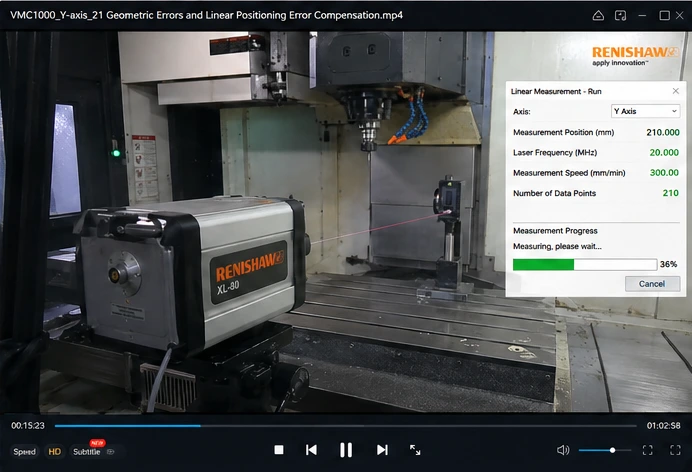
Every linear coordinate axis undergoes bi-directional pitch error cycle testing with measurement targets spaced every 20\text{ mm}. By capturing real-time temperature and atmospheric pressure compensation data, error correction values are written directly into the controller's pitch compensation tables, forcing full-travel positioning accuracy to converge within \le \pm0.003\text{ mm}.
2. Ballbar Circular Interpolation Dynamic Accuracy Testing
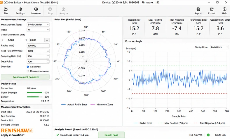
The plotted "circular trace chart" directly exposes backlash at axis reversals, servo mismatch errors, and axis perpendicularity errors. Our factory acceptance standard mandates that at a feed rate of F=1000\text{ mm/min}, the dynamic circularity error must be maintained within 3\ \mu\text{ m}.
3. Spindle Dynamic Balancing and Temperature Rise Monitoring
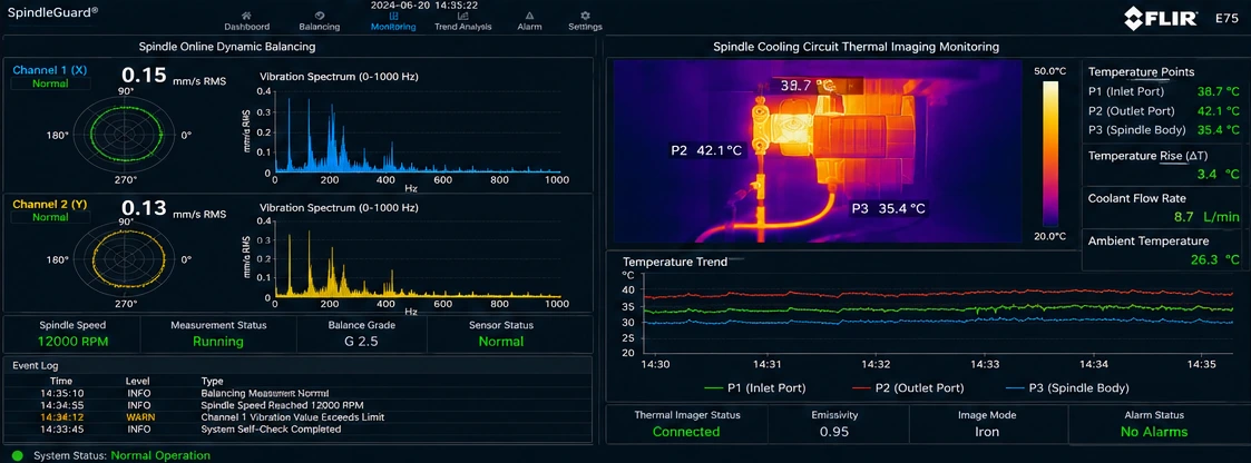
Spindle dynamic balancing calibration is executed at maximum rated operational speed, ensuring the vibration velocity value stays at V_{rms} \le 0.4\text{ mm/s} (conforming to the ISO 1940 G0.4 standard). Concurrently, a constant-temperature oil chiller circulates fluid through the spindle bearings, strictly capping the temperature rise to within +3^\circ\text{C} above ambient temperature, cutting off thermal expansion pathways at the source.
Industrial Application Case Study: High-End Automotive Gearbox Valve Body Die-Casting Mold Machining
- Customer Background: A Tier-1 automotive component supplier in East China, specializing in the manufacturing of aluminum alloy High-Pressure Die Casting (HPDC) molds.
- Technical Bottlenecks Faced: Their existing imported 3-axis milling machine experienced spindle thermal drift when cutting H13 die steel (hardness HRC\ 48-52). This resulted in a 0.04\text{ mm} mismatch on the mold cavity parting line after 12 hours of continuous machining. Consequently, technicians had to spend over 8 hours on manual spot-facing and polishing, and the finish-machined surface roughness Ra could only reach 1.6\ \mu\text{ m}, severely delaying mold delivery cycles.
- Customized Solution: We engineered a tailored VMC-850 High-Precision 5-Axis Machining Center:
- Quantified Feedback Data After 12 Months of Operation:
Technical FAQ: Core Engineering and Procurement Solutions Clarified
Q1: How should I choose between Linear Guides and Box Ways for a CNC milling machine?
A:
- Linear Guides (Roller/Ball): Feature an extremely low friction coefficient (approx. 0.002) and minimal breakaway torque. They are optimized for high-speed, high-frequency directional shifts in light-to-medium-duty precision machining. Modern roller linear guides, due to their line-contact distribution, now provide substantial rigidity.
- Box Ways (Sliding Guideways): Provide massive surface contact area, extreme vibration damping capabilities, and ultra-high load capacities. However, due to the discrepancy between static and dynamic friction (which can cause stick-slip or crawling), their positioning accuracy and traverse speeds (typically \le 20\text{ m/min}) are limited.
- Selection Verdict: Opt for linear guides for complex mold profiles and high-speed non-ferrous metal cutting; select box ways for heavy-duty steel hogging and large depth-of-cut roughing operations.
Q2: How vital is the Through-Spindle Coolant (TSC) function in deep-hole or deep-cavity milling?
A: It is absolutely critical. When milling, drilling, or pocketing at depths exceeding 3 times the tool diameter, standard external flood coolant nozzles cannot overcome the centrifugal force generated by high-speed rotation and the physical obstruction of the workpiece walls to reach the cutting edge.
- TSC (typically pressurized at 20 to 70 bar) blasts high-pressure coolant directly through internal fluid channels inside the cutting tool, using fluid kinetic energy to forcibly evacuate chips out of the cutting zone.
- This effectively prevents chip recutting (where trapped chips are crushed again, causing immediate tool chipping), drops the cutting zone temperature by over 150^\circ\text{C}, extends tool life by 2 to 3 times, and vastly enhances surface roughness.
Q3: How can I quantitatively assess the "Heavy-Duty Cutting Capacity" of a CNC milling machine?
A: Evaluating heavy-milling capabilities requires looking beyond raw rated spindle horsepower. You must perform a combined evaluation of the Spindle Torque Curve and the Net Machine Weight-to-Rigidity Ratio:
- Analyze Low-Speed Torque: Verify if the spindle delivers its maximum torque output at medium-to-low angular velocities (e.g., 500\text{ rpm}) via mechanical reduction gearboxes or dual-speed winding motors, ensuring a low-speed torque output of \ge 500\text{ N·m} to handle heavy roughing.
- Analyze Unit Structural Mass-to-Power Ratio: Heavy-duty cutting unleashes massive structural cutting forces. The machine's net weight (for example, a standard 850-class machine should weigh \ge 5.5\text{ metric tons}) must supply enough physical counter-inertia to prevent micro-elastic deformations throughout the machine bed.
Q4: What is the fundamental technical difference between a 4th Axis and Simultaneous 5-Axis motion?
A:
- 4-Axis / 3+1 Axis Machining: Adds a single rotary axis (typically an A-axis or B-axis table) to the traditional X, Y, and Z linear axes. It is primarily used for positional indexing, where the rotary axis rotates to a set angle and locks into place before 3-axis interpolation takes place. The rotary axis does not move dynamically during the cut.
- Simultaneous 5-Axis Machining: X, Y, Z, and two rotary axes (typically AC or BC combinations) undergo continuous spatial trajectory interpolation simultaneously driven by the controller's RTCP (Rotation Tool Center Point) function. The RTCP algorithm dynamically compensates for spatial tool tip offsets induced by rotary axis angular movements in real time. This is the only viable technical solution for machining impellers, marine propellers, and intricate aerospace turbomachinery components.
Q5: How can coolant management optimize surface corrosion resistance and dimensional stability?
A: Cutting fluids do not merely cool and lubricate; they are a vital control medium for mitigating workpiece thermal deformation:
- Concentration Management: We recommend maintaining a concentration mix of 7\% \sim 10\% for aluminum machining and 5\% \sim 8\% for carbon/alloy steels. Dropping too low risks component rust and poor boundary lubrication; scaling too high compromises heat dissipation and inflates chemical operating costs.
- pH Control: Maintain the fluid pH within a strict range of 8.8 to 9.2. A drop below this threshold indicates rapid bacterial proliferation, leading to fluid degradation (rancidity), which corrodes machine tool guide surfaces and oxidizes finished workpieces.
- Closed-Loop Temperature Control: For high-precision setups, integrating a dedicated coolant fluid chiller is mandatory to match the temperature of the incoming cutting fluid to the thermal mass of the cast iron machine bed (maintaining a delta of \le \pm1^\circ\text{C}). This prevents localized thermal shock and secondary part distortion during machining.
 Email
Email sales1: +86 15312799623