



Regular T-Type vs. Inverted T-Type Horizontal Machining Centers: Key Differences and Selection Guide
When selecting a horizontal machining center, machine structure is an important factor influencing cutting stability, positioning accuracy, axis movement, and overall machining efficiency. Two common structural arrangements are the Regular T-type (Positive T-type) and Inverted T-type horizontal machining centers.
The main difference between regular T-type and inverted T-type horizontal machining centers lies in the machine-bed layout and the arrangement of the moving column and worktable. These differences influence load distribution, moving mass, structural stiffness, and machine configuration.
However, neither design is inherently more accurate, faster, or more rigid. Actual performance depends on the complete machine structure, guideway system, drive configuration, and manufacturing quality.
This guide compares the structural layouts, working principles, machining performance, applications, and maintenance considerations of regular T-type and inverted T-type horizontal machining centers to help you make an informed equipment selection.
1. What Are Regular T-Type and Inverted T-Type Horizontal Machining Centers?
Both regular T-type and inverted T-type horizontal machining centers feature a horizontally oriented spindle and are designed for operations such as milling, drilling, boring, and tapping.
Their main structural difference concerns the arrangement of the bed, moving column, and worktable.
Regular T-type Structure
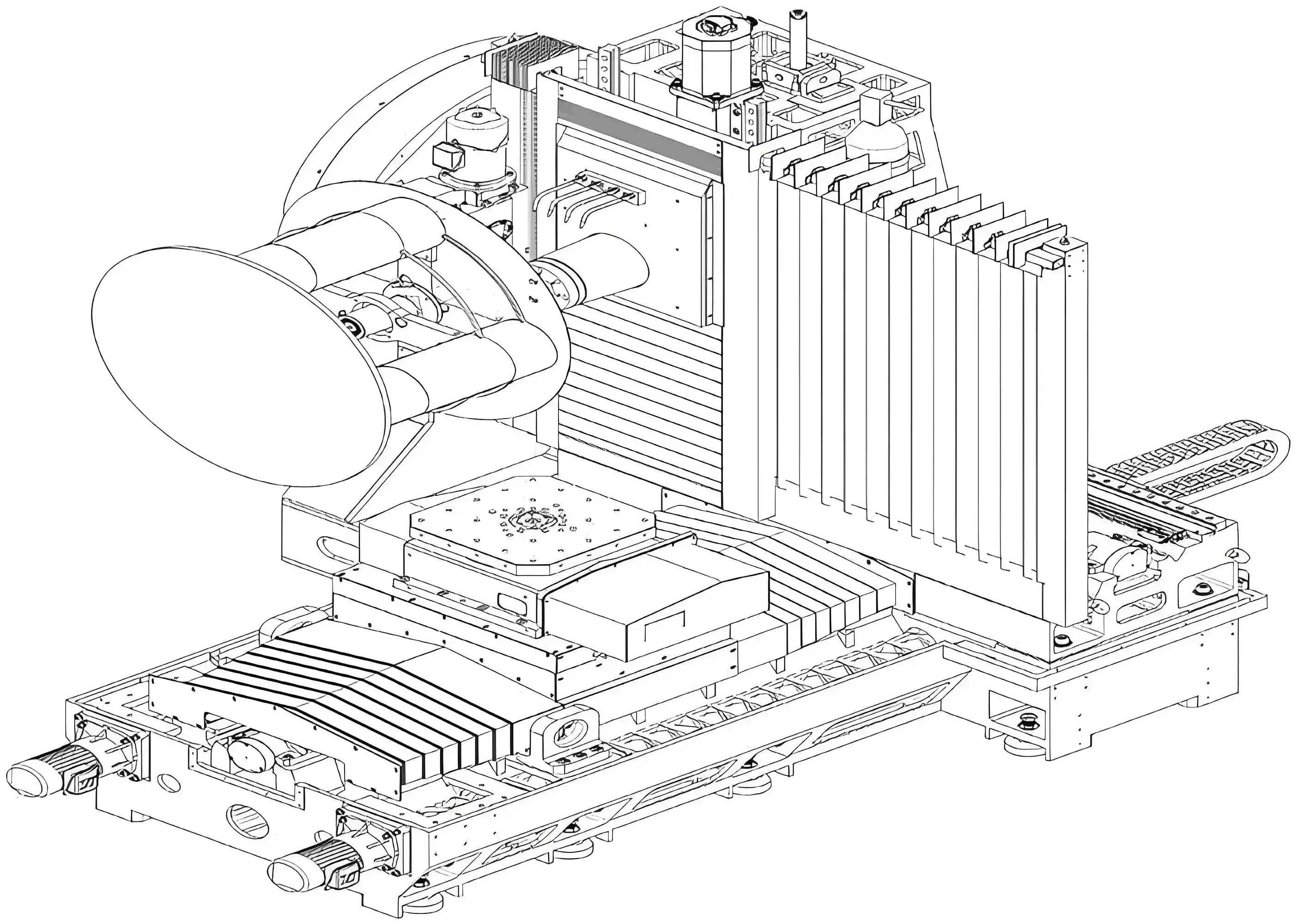
In one commonly documented regular T-type configuration, the machine features a T-shaped bed layout in which:
- The worktable moves along the Z-axis (front and back).
- The column moves along the X-axis (left and right).
- The spindle head moves vertically along the Y-axis.
This arrangement separates the primary horizontal movements between the worktable and column.
The structural design allows engineers to optimize the bed support, column stiffness, and axis-drive arrangement according to the intended machining application.
A regular T-type design can support high rigidity and stable cutting when its bed, guideways, and moving components are appropriately engineered.
Inverted T-type Structure
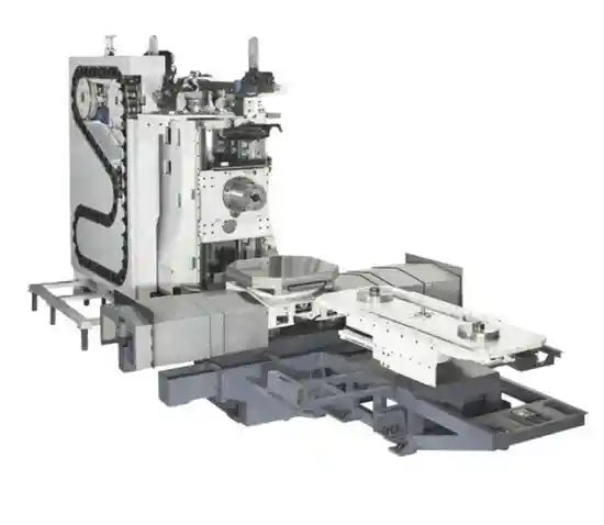
In a corresponding inverted T-type configuration, the moving components are arranged differently:
- The worktable moves along the X-axis (left and right).
- The column moves along the Z-axis (front and back).
- The spindle head moves vertically along the Y-axis.
This arrangement changes how the bed supports the moving components and how the workpiece and spindle approach each other.
Depending on the design, an inverted T-type layout may offer advantages in axis arrangement, machining access, or machine configuration.
However, its performance depends on factors such as moving mass, structural reinforcement, guideway spacing, and drive-system design.
Important: The terms regular T-type and inverted T-type are not used identically by all machine tool manufacturers. The axis arrangements above represent one documented naming convention. Always confirm the actual machine structure using the manufacturer's layout drawings and technical specifications.
2. Key Structural Differences Between Regular T-Type and Inverted T-Type Machines
The two configurations differ primarily in their bed layout, motion-axis arrangement, and mechanical support structure.
Bed Layout
The bed is the foundation of a horizontal machining center. It supports the moving components and transfers machining forces to the machine base and foundation.
Regular T-Type:
In the configuration described above, the bed supports the Z-axis table movement and X-axis column movement.
The location and spacing of the guideways influence how the structure responds to cutting loads and movement.
Inverted T-Type:
The worktable and column move along the opposite horizontal-axis arrangement.
The supporting bed geometry therefore differs, influencing the distribution of structural mass and the arrangement of guideways and drive components.
Both designs may use integrated cast-iron beds with reinforcement ribs, although the exact casting and assembly methods vary by manufacturer.
Guide Rail Configuration
Guideways support linear-axis movement and contribute to the machine's load capacity, rigidity, and positioning performance.
Both regular T-type and inverted T-type machining centers may use:
- Linear ball guideways
- Linear roller guideways
- Hardened sliding guideways
- Other application-specific guideway configurations
Guideway selection depends on the required cutting loads, positioning performance, travel speed, and overall machine design.
The bed layout does not automatically determine whether a machine uses rolling or sliding guideways.
Spindle and Worktable Position
The relative position between the spindle and worktable determines the machine's available working envelope.
Important design factors include:
- Spindle center height
- X-, Y-, and Z-axis travel
- Distance from the spindle nose to the worktable center
- Maximum workpiece dimensions
- Worktable load capacity
- Clearance for workpiece rotation
Neither regular T-type nor inverted T-type construction guarantees a larger working envelope.
These dimensions must be evaluated using the specifications of the actual machine model.
Column and Worktable Movement
The most direct structural distinction is the arrangement of the moving axes.
| Structural Feature | Regular T-Type | Inverted T-Type |
|---|---|---|
| Bed arrangement | Regular T-shaped layout | Inverted T-shaped layout |
| Worktable movement | Z-axis in the example configuration | X-axis in the example configuration |
| Column movement | X-axis in the example configuration | Z-axis in the example configuration |
| Spindle head movement | Vertical Y-axis | Vertical Y-axis |
| Guideway type | Depends on machine design | Depends on machine design |
| Load support | Determined by bed and guideway arrangement | Determined by bed and guideway arrangement |
| Structural performance | Depends on complete machine design | Depends on complete machine design |
Note: Axis assignments and naming should be confirmed against the manufacturer's actual machine drawings.
3. How the Two Structures Affect Machine Operation
Structural differences influence machine operation by changing the arrangement of moving components, drive systems, and load paths.
Motion Transmission
Both configurations commonly use servo motors and mechanical drive systems, such as ball screws, to control axis movement. Some machine designs may use alternative drive technologies.
In a regular T-type configuration, the column and worktable move along their designated axes to position the tool relative to the workpiece.
An inverted T-type machine achieves the same machining objective through a different arrangement of moving components.
The resulting motion performance depends on:
- Moving component mass
- Axis-drive power and torque
- Ball-screw or linear-drive specifications
- Guideway configuration
- Acceleration and deceleration settings
- CNC control performance
A shorter transmission path or lighter moving component may improve responsiveness in a particular design, but such benefits must be verified using actual machine specifications.
Load-Bearing and Cutting Force Distribution
During machining, cutting forces act on both the tool and workpiece.
These forces are transmitted through the spindle, spindle head, column, worktable, guideways, and bed structure.
The arrangement of these components determines how mechanical loads are distributed.
Regular T-Type:
The particular arrangement of column and table movement influences the machine's support geometry and structural deformation under load.
Inverted T-Type:
The alternative arrangement changes the location of moving masses and load-bearing components, which may affect deflection and vibration characteristics.
Neither structure can be assumed to distribute loads more effectively without examining its actual geometry, guideway spacing, and structural reinforcement.
Structural Balance and Moving Mass
Moving mass affects acceleration, deceleration, and servo response.
A heavier moving assembly generally requires greater driving force to achieve the same acceleration.
Therefore, both configurations should be evaluated according to which components move along each axis and how much mass the drive system must accelerate.
Vertical-axis balancing systems, such as counterweights or hydraulic balancing devices, may be used to support the spindle head or other vertical moving components.
These systems are determined by the machine's vertical-axis design rather than by the regular or inverted T designation alone.
Key difference: The two layouts distribute axis movement and structural mass differently, but their actual operating performance depends on the engineering of the complete machine.
4. Performance Comparison: Rigidity, Accuracy, and Dynamic Response
The structural differences between regular T-type and inverted T-type machining centers may influence cutting performance, but the results vary between machine models.
Rigidity and Cutting Stability
Machine rigidity refers to the ability of the structure to resist deformation under cutting forces.
Regular T-Type:
A well-designed regular T-type machine can provide high rigidity through a reinforced bed, appropriately supported column, and suitable guideway arrangement.
Such configurations may be designed for demanding machining operations, including heavy milling and boring.
Inverted T-Type:
An inverted T-type machine can also achieve high structural rigidity through optimized guideway support, column design, and reinforcement.
Some inverted T-type configurations are specifically designed for high-load machining and precision applications.
Comparison: Neither layout is inherently superior in static or dynamic rigidity. Relevant factors include spindle overhang, structural stiffness, moving-component mass, natural frequencies, and vibration damping.
Positioning and Machining Accuracy
Machine accuracy depends on the complete motion and feedback system rather than the T-shaped bed arrangement alone.
Important factors include:
- Guideway manufacturing and installation accuracy
- Ball-screw and drive-system performance
- Position feedback and compensation
- Machine geometry
- Thermal stability
- Spindle and rotary-table accuracy
For an objective comparison, buyers should request manufacturer-provided positioning accuracy and repeatability data.
The ISO 10791-4 standard provides methods for evaluating positioning accuracy and repeatability of machining-center axes.
Dynamic Response and Movement Speed
The dynamic performance of a machining center influences axis acceleration, rapid traverse, and positioning efficiency.
Regular T-Type:
Its axis arrangement may allow a particular design to optimize moving-column mass and acceleration performance.
Inverted T-Type:
The alternative axis arrangement may support different drive and structural optimization strategies.
However, neither configuration guarantees faster rapid traverse or shorter acceleration times.
Performance depends on moving mass, drive capability, guideway friction, and controller settings.
Performance Comparison Summary
| Performance Factor | Regular T-Type | Inverted T-Type |
|---|---|---|
| Static rigidity | Depends on structure and support design | Depends on structure and support design |
| Dynamic stiffness | Influenced by moving mass and structural design | Influenced by moving mass and structural design |
| Positioning accuracy | Determined by machine-specific specifications | Determined by machine-specific specifications |
| Rapid traverse | Depends on drive and moving components | Depends on drive and moving components |
| Heavy-cutting capability | Possible with suitable structural design | Possible with suitable structural design |
| Thermal stability | Depends on machine geometry and thermal design | Depends on machine geometry and thermal design |
The most reliable comparison is between actual machine models under comparable operating and measurement conditions.
5. Application Scenarios: Which Structure Suits Your Needs?
Both regular T-type and inverted T-type horizontal machining centers can support a wide range of machining operations.
The most suitable configuration depends on workpiece characteristics, cutting requirements, machining accuracy, and production conditions.
Heavy-duty Cutting
Heavy-duty machining requires sufficient spindle torque, structural rigidity, and workpiece support.
Applications may include:
- Gearbox housings
- Large cast-iron components
- Industrial machinery frames
- Heavy equipment parts
When comparing T-type structures for heavy-duty cutting, evaluate:
- Maximum worktable load
- Spindle torque and power
- Guideway type and spacing
- Structural rigidity
- Workpiece size and center of gravity
A regular T-type machine may be suitable for heavy-duty machining, but an appropriately designed inverted T-type machine can also support substantial cutting loads.
Precision Machining
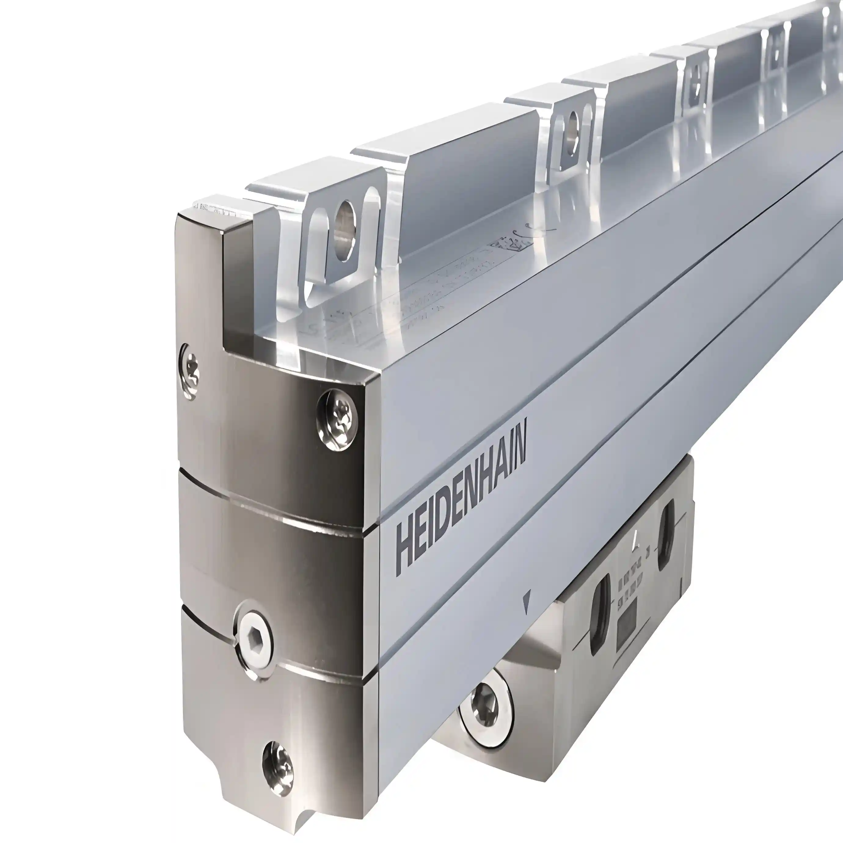
(optical scale)
Precision machining requires stable positioning, repeatability, thermal performance, and reliable mechanical alignment.
Typical applications include:
- Precision gearbox components
- Aerospace parts
- Mold and die components
- Complex multi-face workpieces
An inverted T-type machine may be designed for high-precision applications, but this capability is not exclusive to that configuration.
Both types can use advanced position feedback, precision guideways, and thermal compensation systems.
For applications requiring tight tolerances, compare actual machining-test results rather than assuming one structure provides higher accuracy.
Production Mode and Automation
Horizontal machining centers are commonly used in both batch production and flexible manufacturing.
Mass Production:
Important considerations include pallet-changing systems, automation compatibility, cycle time, and machine reliability.
Small-Batch, High-Mix Production:
Important factors include setup accessibility, workpiece accommodation, programming flexibility, and changeover efficiency.
Both regular T-type and inverted T-type machining centers can support automatic pallet changers and production automation, depending on the machine design.
How to Choose the Right Structure
Before selecting a machine, evaluate the following requirements:
| Selection Factor | What to Check |
|---|---|
| Workpiece dimensions | Maximum machining envelope and axis travel |
| Workpiece weight | Rated pallet load and load distribution |
| Machining accuracy | Positioning and repeatability test results |
| Cutting requirements | Spindle torque, power, and machine rigidity |
| Production efficiency | Rapid traverse, tool-changing time, and cycle time |
| Automation | Pallet changer and loading-system compatibility |
| Workshop layout | Machine footprint and service access |
Selection recommendation: Do not choose a regular T-type or inverted T-type machine solely because one is described as suitable for heavy cutting and the other for precision machining. Select the configuration that meets your verified technical and production requirements.
6. Manufacturing Costs and Maintenance Considerations
Machine purchase cost and long-term maintenance requirements are important when comparing horizontal machining center structures.
Manufacturing Cost
Both configurations require precision-machined structural components, accurate guideway installation, and reliable drive systems.
Manufacturing costs depend on factors such as:
- Bed casting size and complexity
- Reinforcement and structural machining
- Guideway and ball-screw specifications
- Worktable and pallet systems
- CNC control and automation options
- Machine assembly and calibration requirements
One structure should not be assumed to cost a fixed percentage more than the other.
Actual pricing depends on the complete equipment configuration and manufacturer.
Maintenance Convenience
Both regular T-type and inverted T-type machining centers require routine inspection and maintenance.
Important maintenance areas include:
Guideways: Check lubrication performance, guideway protection, and contamination.
Ball Screws and Drive Systems: Monitor abnormal noise, backlash, lubrication condition, and positioning performance.
Worktable and Rotary Systems: Inspect clamping performance, indexing accuracy, and relevant hydraulic or mechanical components.
Chip Management: Ensure that chips and coolant do not interfere with guideways, covers, or moving components.
Access and Serviceability: Confirm that maintenance personnel can safely access key components.
Maintenance intervals depend on the machine manufacturer's instructions, operating hours, machining environment, and component condition.
Total Cost of Ownership
When comparing regular T-type and inverted T-type machines, consider the complete cost of ownership:
- Initial purchase and installation
- Expected machining productivity
- Energy consumption
- Preventive maintenance
- Spare-parts availability
- Equipment downtime
- Long-term accuracy retention
A machine with a higher initial price may provide better value if it meets production requirements more efficiently and requires less unplanned maintenance.
7. Conclusion: Choosing Between Regular T-Type and Inverted T-Type Horizontal Machining Centers
The primary difference between regular T-type and inverted T-type horizontal machining centers is their machine-bed layout and the arrangement of moving axes.
These structural differences affect how the machine supports its moving components, distributes cutting forces, and accommodates drive systems.
However, the bed layout alone does not determine machining accuracy, rigidity, speed, or load capacity.
When comparing the two configurations, focus on:
- Actual axis movement and structural layout
- Workpiece dimensions and load capacity
- Spindle performance and cutting capability
- Positioning accuracy and repeatability
- Machine rigidity and dynamic performance
- Automation, maintenance, and long-term operating costs
Neither regular T-type nor inverted T-type construction is universally superior. The right choice depends on how the complete machine design matches your machining requirements.
For assistance comparing horizontal machining center configurations, contact MINNUO to discuss your workpiece specifications, machining processes, and equipment requirements.
Frequently Asked Questions (FAQ)
Q1. What is the main difference between regular T-type and inverted T-type horizontal machining centers?
A:The main difference lies in the bed layout and the arrangement of the moving column and worktable. In one commonly documented convention, a regular T-type machine has a Z-axis moving table and X-axis moving column, while an inverted T-type machine uses the opposite arrangement. Naming can vary by manufacturer.
Q2. Is a regular T-type horizontal machining center better for heavy cutting?
A:Not necessarily. Heavy-cutting capability depends on spindle torque, machine rigidity, guideway support, and worktable capacity. Both regular T-type and inverted T-type machines can be designed for heavy-duty machining.
Q3. Which structure provides higher machining accuracy?
A:Neither structure automatically provides higher accuracy. Positioning accuracy and repeatability depend on the guideways, drive system, machine geometry, thermal stability, and manufacturing quality. Compare verified specifications from actual machine models.
Q4. Are inverted T-type horizontal machining centers faster?
A:Not always. Axis movement speed and acceleration depend on the moving mass, servo system, guideway design, and controller settings. The inverted T-type arrangement does not inherently guarantee faster operation.
Q5. What should buyers consider when choosing between the two structures?
A:Buyers should compare workpiece size, table load capacity, spindle performance, axis travel, positioning accuracy, machining requirements, automation options, and maintenance needs. The final choice should be based on machine-specific performance

 Email
 sales1: +86 15312799623