CNC Milling Machine Working Principles & Basic Operations
CNC (Computer Numerical Control) milling machines have revolutionized modern manufacturing, delivering unmatched precision, efficiency, and consistency in shaping a wide range of materials—from metals and plastics to composites. Whether you're a beginner learning the ropes of CNC machining, a machinist looking to refine your skills, or a business owner seeking to understand how these machines drive production, grasping the core working principles and basic operations is essential. This comprehensive guide breaks down the fundamentals of CNC milling, from the science behind its operation to step-by-step instructions for basic tasks, ensuring you gain a clear, practical understanding of how these powerful tools work.
Unlike traditional manual milling machines, which rely on human operators to guide the cutting tool and workpiece, CNC milling machines use pre-programmed digital instructions to automate the machining process. This automation eliminates human error, enables complex part production, and ensures consistent results across large batches—making CNC milling indispensable in industries like aerospace, automotive, medical device manufacturing, and prototyping. By the end of this guide, you'll be able to explain how a CNC milling machine works, identify its key components, and perform basic operations with confidence.
What Is a CNC Milling Machine? A Brief Overview
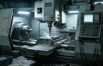
A CNC milling machine is a computer-controlled cutting tool designed to remove material from a solid workpiece to create custom shapes, holes, slots, and contours. The term “CNC” refers to Computer Numerical Control, which means the machine's movements and operations are guided by numerical code (G-code and M-code) generated from CAD (Computer-Aided Design) and CAM (Computer-Aided Manufacturing) software. This code translates the designer's digital model into precise, repeatable movements of the machine's axes and cutting tool.
At its core, CNC milling operates on the principle of subtractive manufacturing—removing material from a raw workpiece (often a block of metal, plastic, or wood) to achieve the desired final shape. Unlike additive manufacturing (3D printing), which builds parts layer by layer, subtractive manufacturing starts with a solid material and trims away excess to form the part. This approach is ideal for producing high-precision components with tight tolerances, making it a staple in industries that demand reliability and accuracy.
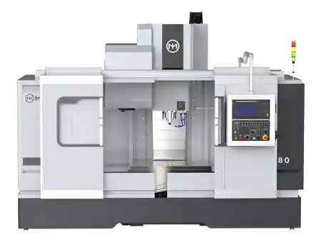
CNC milling machines come in various configurations, including vertical (VMC), horizontal (HMC), benchtop, and 5-axis models, but all share the same basic working principles and core components. Regardless of the type, every CNC milling machine relies on three key elements: a computerized control system, a cutting tool (mounted on a spindle), and a workpiece (secured to a worktable). These elements work together to execute the machining process with precision and efficiency.
Core Working Principles of a CNC Milling Machine
To understand how a CNC milling machine works, it's critical to break down its core principles—from the translation of digital code to the physical cutting of material. Below are the fundamental principles that govern every CNC milling operation, explained in simple, practical terms.
1. Subtractive Manufacturing: The Foundation of Milling
As mentioned earlier, CNC milling is a subtractive manufacturing process. This means the machine uses a rotating cutting tool to remove material from the workpiece in controlled increments. The cutting tool (e.g., end mill, face mill, drill bit) spins at high speeds (measured in RPM—revolutions per minute) and moves relative to the workpiece along multiple axes (X, Y, Z, and sometimes rotational axes for advanced models) to carve out the desired shape.
The key to subtractive manufacturing in CNC milling is precision control. Every movement of the cutting tool and workpiece is guided by the CNC program, ensuring that material is removed only where needed. This level of control is impossible with manual milling, where human error can lead to inconsistent cuts, wasted material, and flawed parts. For example, when machining a complex aerospace component, the CNC machine can remove material in fractions of a millimeter, ensuring the part meets the strictest tolerance requirements.
2. CNC Programming: From Digital Design to Machine Instructions
The heart of CNC milling is the CNC program—a set of numerical instructions that tells the machine how to move, when to cut, and what parameters to use (e.g., spindle speed, feed rate). This program is generated using CAD/CAM software, which bridges the gap between the designer's digital model and the machine's physical operation.
The programming process follows three key steps:
- CAD Design: First, a 2D or 3D model of the part is created using CAD software (e.g., SolidWorks, AutoCAD, Fusion 360). This model includes all dimensions, contours, and tolerances required for the final part. CAD models ensure precise communication between engineers and machinists, serving as the blueprint for the machining process.
- CAM Programming: The CAD model is then imported into CAM software (e.g., Mastercam, GibbsCAM), which converts the design into a toolpath. The CAM software calculates the optimal path for the cutting tool, considering factors like material type, tool size, and desired surface finish. This step also involves setting machining parameters, such as spindle speed, feed rate, and cutting depth.
- G-Code Generation: The CAM software translates the toolpath into G-code—the standard programming language for CNC machines. G-code consists of lines of code (called “blocks”) that include commands for axis movements, spindle control, tool changes, and coolant activation. Each line of G-code corresponds to a specific action (e.g., “G01 X10 Y5 F200” means move the tool linearly to coordinates X10, Y5 at a feed rate of 200 mm/min). M-code (miscellaneous code) is also used for auxiliary functions like turning the spindle on/off or activating coolant.
Once the G-code is generated, it is loaded into the CNC machine's control panel (either via USB, network, or direct input). The machine's controller then interprets the code and sends signals to the machine's motors and actuators to execute the desired movements.
3. Axis Movement: The Key to Precision
CNC milling machines move the cutting tool and workpiece along multiple axes to achieve complex shapes. The number of axes varies by machine type, but the most common configurations are 3-axis, 4-axis, and 5-axis. Each axis represents a direction of movement, and the machine's controller coordinates these movements to follow the toolpath precisely.
Here's a breakdown of the standard axes:
- X-Axis: Horizontal movement (left/right) of the worktable or spindle.
- Y-Axis: Vertical movement (forward/backward) of the worktable or spindle.
- Z-Axis: Vertical movement (up/down) of the spindle, which controls the cutting depth.
- Rotational Axes (A, B, C): Found in 4-axis and 5-axis machines, these axes rotate the workpiece or spindle to allow access to multiple sides of the part without repositioning. For example, the A-axis rotates around the X-axis, while the C-axis rotates around the Z-axis. This enables the machining of complex geometries like turbine blades and medical implants that require multi-angle cuts.
The machine's controller uses interpolation (linear, circular, or helical) to calculate the exact path between two points, ensuring smooth, precise movement. For example, linear interpolation is used for straight cuts, while circular interpolation is used for arcs and curves. This interpolation ensures that the cutting tool follows the toolpath accurately, even when moving along multiple axes simultaneously.
4. Spindle Operation: Powering the Cutting Tool
The spindle is the “engine” of the CNC milling machine, responsible for rotating the cutting tool at high speeds. The spindle's speed (RPM) is controlled by the CNC program and varies based on the material being machined and the type of cutting tool used. For example, soft materials like aluminum require higher spindle speeds (10,000–20,000 RPM), while hard materials like steel require lower speeds (5,000–10,000 RPM) but higher torque to cut through the material effectively.
Spindles are typically driven by servo motors, which provide precise speed control and torque. The spindle also features a taper (e.g., BT30, BT40, BT50) that connects to the tool holder, ensuring the cutting tool is securely mounted and aligned. A secure connection is critical to prevent tool vibration, which can damage the tool, workpiece, and machine, and reduce the quality of the cut.
5. Feedback Control: Ensuring Accuracy
To maintain precision, modern CNC milling machines usefeedback control systems (closed-loop or semi-closed-loop). These systems use sensors (e.g., encoders, linear scales) to monitor the position and speed of the machine's axes and spindle in real time. The sensor data is sent back to the controller, which compares the actual position to the desired position (from the G-code) and makes adjustments to correct any errors.
Closed-loop systems are the most precise, as they monitor the actual position of the moving components (e.g., worktable, spindle) and adjust accordingly. Semi-closed-loop systems monitor the position of the motor's output shaft, which is less precise but more cost-effective. This feedback control ensures that the machine maintains accuracy even during long machining runs, reducing waste and improving part quality.
Key Components of a CNC Milling Machine (How They Work Together)
A CNC milling machine is made up of several interconnected components, each playing a critical role in the machining process. Understanding these components and how they work together is essential for mastering basic operations and troubleshooting common issues. Below are the key components, explained in detail:
1. CNC Controller
The CNC controller is the “brain” of the machine, responsible for interpreting the G-code, controlling axis movements, and managing all machine operations. It features a user-friendly interface (touchscreen or keypad) that allows operators to load programs, adjust parameters, and monitor the machining process. Popular controller brands include Fanuc, Siemens, Haas, and Mitsubishi, each with slightly different interfaces but the same core functionality.
The controller's main functions include: decoding G-code, coordinating axis movements, controlling spindle speed and feed rate, managing tool changes, and providing error feedback. Advanced controllers also offer features like tool life monitoring, remote monitoring, and adaptive machining, which adjusts parameters in real time to optimize performance.
2. Spindle Assembly
The spindle assembly consists of the spindle motor, spindle housing, and tool holder. As mentioned earlier, the spindle rotates the cutting tool at high speeds, and its speed and torque are controlled by the CNC program. The spindle housing is designed to reduce vibration, which is critical for precision. Tool holders (e.g., collets, end mill holders) secure the cutting tool to the spindle, ensuring alignment and stability during cutting. The spindle taper (BT30, BT40, etc.) must match the tool holder to ensure a secure fit.
3. Worktable
The worktable is the surface where the workpiece is mounted and secured. It moves along the X and Y axes (in 3-axis machines) to position the workpiece relative to the cutting tool. Worktables are typically made of high-strength steel or cast iron to withstand the forces of machining and maintain stability. They feature T-slots or holes that allow the use of clamps, vises, or fixtures to secure the workpiece firmly—preventing movement during cutting, which could lead to errors or accidents.
In some machines (e.g., horizontal milling machines), the worktable may also rotate (A-axis or B-axis) to allow multi-sided machining. The maximum weight capacity of the worktable varies by machine size, so it's important to ensure the workpiece does not exceed this limit to avoid damage.
4. Axes Drive System
The axes drive system is responsible for moving the worktable and spindle along the X, Y, Z, and rotational axes. It consists of servo motors, ball screws, and linear guides. Servo motors convert electrical signals from the controller into mechanical movement, providing precise control over speed and position. Ball screws are used to convert rotational motion (from the servo motor) into linear motion (of the worktable or spindle), ensuring smooth, accurate movement. Linear guides reduce friction between moving parts, further improving precision and reducing wear and tear.
5. Cutting Tools
Cutting tools are the “teeth” of the CNC milling machine, responsible for removing material from the workpiece. The type of tool used depends on the material being machined and the desired cut (e.g., face milling, slotting, drilling). Common cutting tools include:
- End Mills: Used for slotting, profiling, and contouring. They have cutting edges on the end and sides, allowing for both vertical and horizontal cuts.
- Face Mills: Used for machining flat surfaces (faces) on the workpiece. They have cutting edges on the bottom and sides, covering a larger area for faster material removal.
- Drill Bits: Used for drilling holes in the workpiece. They are available in various sizes and styles (e.g., twist drills, center drills) to accommodate different hole diameters.
- Tap Tools: Used for cutting internal threads in holes. They are paired with drilling tools to create threaded holes.
Cutting tools are made from high-speed steel (HSS), carbide, or ceramic, with carbide being the most common for industrial applications due to its durability and heat resistance. The tool's geometry (e.g., number of flutes, helix angle) also affects performance—more flutes provide a smoother finish, while a steeper helix angle is better for cutting soft materials.
6. Coolant System
The coolant system is essential for maintaining tool life and part quality. During machining, the cutting tool generates significant heat, which can damage the tool, warp the workpiece, or reduce the surface finish. The coolant system sprays a mixture of oil and water (or synthetic coolant) onto the cutting tool and workpiece, cooling them down, lubricating the cutting surface, and flushing away chips (metal shavings) from the cutting area.
Coolant is typically stored in a reservoir and pumped through nozzles positioned near the cutting tool. The CNC program can be set to activate the coolant automatically when machining starts, ensuring consistent cooling throughout the process. Proper coolant maintenance (e.g., changing the coolant regularly, checking for contamination) is critical to prevent tool wear and maintain machine performance.
7. Automatic Tool Changer (ATC)
Many CNC milling machines (especially industrial-grade models) feature an Automatic Tool Changer (ATC), which allows the machine to switch between cutting tools automatically during machining. The ATC stores multiple tools in a magazine or carousel and retrieves the required tool based on the G-code instructions. This eliminates the need for manual tool changes, reducing setup time and improving efficiency—especially for complex parts that require multiple tools.
The ATC's tool capacity varies by machine, ranging from 10–20 tools for basic models to 40+ tools for industrial models. The tool change time (typically 1–5 seconds) is an important factor for high-volume production, as faster tool changes reduce cycle time. Common ATC types include carousel-style (slower, lower capacity) and swing-arm-style (faster, higher capacity).
Basic CNC Milling Operations: Step-by-Step Guide
Now that you understand the working principles and key components of a CNC milling machine, let's walk through the basic operations—from setup to finishing. These steps apply to most 3-axis CNC milling machines and are essential for anyone learning to operate a CNC mill. Always follow the machine's operator manual and safety guidelines before performing any operations.
Step 1: Machine Startup and Preparation
Before starting the machine, perform a pre-operation check to ensure everything is in working order. This step is critical for safety and preventing damage to the machine or workpiece:
Turn On the Machine: Switch on the main power supply and the CNC controller. Wait for the controller to boot up (this may take a few minutes). Ensure the emergency stop button is not engaged (it should be in the “out” position).
Check the Coolant System: Verify that the coolant reservoir is full and that the coolant lines are clear of debris. Test the coolant pump to ensure it sprays properly onto the cutting area.
Inspect the Spindle and Tools: Check that the spindle is clean and free of debris. Ensure the cutting tools are properly mounted in the tool holder and that the tool holder is securely attached to the spindle. Inspect the tools for wear or damage (e.g., chipped edges), and replace any damaged tools.
Check the Worktable: Clean the worktable of any chips or debris. Ensure the T-slots or clamps are in good condition and that the worktable moves smoothly along the X and Y axes (test using manual mode).
Load the CNC Program: Load the G-code program into the controller via USB, network, or direct input. Review the program to ensure there are no errors (e.g., incorrect coordinates, missing commands). Many controllers allow you to simulate the program (without cutting) to verify the toolpath.
Step 2: Workpiece Setup and Clamping
Properly securing the workpiece is essential for precision and safety. A loose workpiece can move during machining, causing errors, tool damage, or even accidents. Follow these steps to set up and clamp the workpiece:
Select the Right Fixture: Choose a fixture (e.g., vise, clamp, custom jig) that matches the size and shape of the workpiece. For small, flat workpieces, a bench vise is ideal. For larger or irregular workpieces, use custom clamps or jigs to ensure stability.
Position the Workpiece: Place the workpiece on the worktable, ensuring it is aligned with the machine's axes. Use a edge finder or dial indicator to align the workpiece precisely (this ensures the toolpath matches the workpiece's position).
Clamp the Workpiece: Secure the workpiece using the fixture, ensuring it is tight enough to prevent movement but not so tight that it warps the workpiece. Check the workpiece for movement by gently pushing or pulling it—if it moves, adjust the clamps.
Verify the Workpiece Position: Use the machine's manual mode to move the spindle (with the tool mounted) near the workpiece and verify that the toolpath will not collide with the clamps or fixture. This is critical to avoid damage to the tool, workpiece, or machine.
Step 3: Tool Setting (Tool Length and Work Offset)
Tool setting is the process of calibrating the cutting tool's position relative to the workpiece. This ensures the machine knows the exact location of the tool, allowing it to make precise cuts. There are two key types of tool setting: tool length offset and work offset.
Tool Length Offset: This compensates for the length of the cutting tool. To set the tool length offset:
- Mount the tool in the spindle.
- Use a tool length setter (a device that measures the tool's length) or a touch probe to measure the distance from the spindle nose to the tool's tip.
- Enter the measured length into the controller's tool offset table (this is usually stored as H-code, e.g., H01 for tool 1).
Work Offset: This sets the origin (zero point) of the workpiece coordinate system. The origin is the point from which the machine measures all movements (X, Y, Z). To set the work offset:
- Use an edge finder or touch probe to find the X and Y origin (typically the corner of the workpiece).
- Move the tool to the Z origin (the top surface of the workpiece) and set the Z offset.
- Enter the offset values into the controller's work offset table (usually stored as G54–G59 codes).
Tool setting is a critical step—incorrect offsets can lead to incorrect cuts, wasted material, or tool damage. Always double-check the offset values before starting the machining process.
Step 4: Program Simulation and Dry Run
Before starting the actual machining, it's important to simulate the program and perform a dry run (machining without cutting material) to verify the toolpath and avoid collisions. This step is especially important for complex programs or when using a new tool.
Program Simulation: Use the controller's simulation feature to visualize the toolpath on the screen. This allows you to check for errors (e.g., incorrect coordinates, tool collisions) without moving the machine.
Dry Run: Perform a dry run by setting the machine to manual mode or using the dry run function. This runs the program without the spindle rotating or the coolant flowing. Watch the machine's movements to ensure the toolpath is correct and that there are no collisions with the workpiece, clamps, or fixture. Adjust the program if necessary.
Step 5: Machining Operation
Once the setup, tool setting, and simulation are complete, you're ready to start the actual machining. Follow these steps to run the program:
Set the Machining Parameters: Ensure the spindle speed, feed rate, and cutting depth are set correctly in the program. These parameters should be based on the material being machined and the type of tool used (e.g., higher speed for aluminum, lower speed for steel).
Start the Spindle: Press the spindle start button (or use the M03 G-code command) to start the spindle rotating at the programmed speed. Verify that the spindle is rotating in the correct direction (clockwise or counterclockwise).
Activate Coolant: Turn on the coolant system (or use the M08 G-code command) to cool the tool and workpiece and flush away chips.
Start the Program: Switch the machine to automatic mode and press the cycle start button to run the program. Monitor the machining process closely, checking for any unusual sounds (e.g., grinding, squealing) or vibrations. If you notice any issues, press the feed hold or emergency stop button immediately.
Monitor Chip Removal: Ensure chips are being flushed away by the coolant. If chips accumulate around the cutting area, stop the machine and clean them away to prevent tool damage or poor cut quality.
Step 6: Post-Machining Tasks
Once the program has finished running, perform these post-machining tasks to ensure the workpiece is complete and the machine is ready for the next job:
Stop the Spindle and Coolant: Press the spindle stop button (or use the M05 G-code command) and turn off the coolant (M09 G-code command).
Remove the Workpiece: Loosen the clamps and carefully remove the workpiece from the worktable. Inspect the workpiece for quality—check dimensions, surface finish, and tolerances using measuring tools (e.g., calipers, micrometers, gauge blocks).
Clean the Machine: Remove chips from the worktable, spindle, and cutting area using a brush or air compressor. Wipe down the worktable with a clean cloth to remove coolant residue.
Store Tools and Fixtures: Remove the cutting tools from the spindle and store them in a tool cabinet. Clean the fixtures and return them to their storage location.
Shut Down the Machine: Turn off the CNC controller and the main power supply. Ensure the machine is in a safe state (e.g., worktable in a neutral position, spindle retracted) before leaving.
Common CNC Milling Operations Explained
CNC milling machines can perform a wide range of operations, depending on the tool used, the axis configuration, and the program. Below are the most common basic operations, along with their purposes and applications:
1. Face Milling
Face milling is the process of machining a flat surface (face) on the top or side of the workpiece. It uses a face mill tool, which has cutting edges on the bottom and sides. Face milling is used to create a smooth, flat surface, often as a starting point for other operations (e.g., drilling, slotting). It is commonly used in automotive and aerospace manufacturing to machine engine blocks, brackets, and other flat components. The key parameters for face milling include spindle speed, feed rate, and cutting depth—higher feed rates are used for faster material removal, while slower speeds are used for a smoother finish.
2. Peripheral Milling (Slab Milling)
Peripheral milling (also called slab milling) is used to machine flat surfaces parallel to the worktable. It uses an end mill or slab mill tool, with cutting edges on the side of the tool. The tool rotates, and the worktable moves along the X or Y axis to remove material. Peripheral milling is ideal for machining large flat surfaces, such as the sides of a workpiece or the surface of a mold. It can also be used to create slots or grooves by adjusting the cutting depth and tool path.
3. Slotting
Slotting is the process of cutting a narrow groove or slot in the workpiece. It uses an end mill tool (usually with two or four flutes) to cut along the Z-axis (vertical) and then along the X or Y axis (horizontal) to create the slot. Slotting is used in a variety of applications, such as creating keyways (for gears and shafts), grooves for O-rings, and slots for fasteners. The width of the slot is determined by the diameter of the end mill, while the depth is controlled by the Z-axis movement. For wider slots, multiple passes may be required.
4. Drilling
Drilling is the process of creating a round hole in the workpiece. It uses a drill bit tool, which rotates at high speed and moves along the Z-axis to penetrate the material. Drilling is a common operation in almost all manufacturing industries, used to create holes for fasteners (screws, bolts), pipes, or other components. The size of the hole is determined by the diameter of the drill bit. For precise holes, drilling is often followed by reaming (to smooth the hole) or tapping (to add threads).
5. Tapping
Tapping is the process of cutting internal threads in a hole. It uses a tap tool, which has thread-cutting edges. The tap is mounted in the spindle and rotated clockwise (for right-hand threads) or counterclockwise (for left-hand threads) while moving along the Z-axis. Tapping is used to create threaded holes for screws, bolts, or other fasteners. It is often performed after drilling, as the hole must be pre-drilled to the correct size before tapping. The thread size (e.g., M8, 1/4-20) is determined by the tap size.
6. Contour Milling
Contour milling is used to machine complex curves, arcs, or irregular shapes on the workpiece. It uses an end mill tool and relies on the machine's interpolation capabilities to follow the contour of the part. Contour milling is commonly used in mold making, aerospace, and medical device manufacturing to create complex shapes like turbine blades, mold cavities, and orthopedic implants. The toolpath for contour milling is generated by the CAM software, which ensures the tool follows the exact shape of the CAD model.
Safety Guidelines for CNC Milling Operations
CNC milling machines are powerful tools that can cause serious injury if not operated safely. It is critical to follow these safety guidelines to protect yourself, others, and the machine:
- Wear Proper Personal Protective Equipment (PPE): Always wear safety glasses to protect your eyes from chips and coolant. Use ear protection if the machine is loud (above 85 dB). Avoid loose clothing, jewelry, or long hair, which can get caught in moving parts. Do not wear gloves while operating the machine, as they can get caught in the spindle or tool.
- Never Reach Into the Cutting Area During Operation: Keep your hands and body away from the spindle, cutting tool, and moving parts while the machine is running. Use tools (e.g., pliers, brushes) to remove chips or adjust the workpiece only when the machine is stopped.
- Use the Emergency Stop Button When Needed: Familiarize yourself with the location of the emergency stop button (usually red and prominent). Press it immediately if you notice any issues (e.g., tool breakage, workpiece movement, unusual sounds).
- Never Operate a Machine Without Training: Only trained operators should operate a CNC milling machine. If you are a beginner, work with a qualified instructor until you are comfortable with the basic operations.
- Keep the Work Area Clean and Organized: A cluttered work area increases the risk of accidents. Keep chips, tools, and other debris off the worktable and floor. Ensure there is enough space around the machine to move freely.
- Inspect the Machine Before Each Use: Check for loose parts, damaged tools, or coolant leaks before starting the machine. Report any issues to a supervisor or maintenance personnel immediately.
- Never Modify the Machine or Program Without Permission: Modifying the machine's components or the CNC program can lead to accidents or damage. Always get permission from a supervisor before making any changes.
Troubleshooting Common CNC Milling Issues
Even with proper setup and operation, issues can arise during CNC milling. Below are some common problems and their solutions to help you troubleshoot quickly:
- Poor Surface Finish: This is often caused by dull tools, incorrect spindle speed/feed rate, or vibration. Solution: Replace the tool, adjust the spindle speed and feed rate, or check for loose components (e.g., tool holder, clamps) to reduce vibration.
- Tool Breakage: Tool breakage can be caused by excessive cutting depth, incorrect spindle speed, or a dull tool. Solution: Reduce the cutting depth, adjust the spindle speed to match the material, and replace dull tools.
- Incorrect Part Dimensions: This is usually due to incorrect tool offsets, workpiece misalignment, or program errors. Solution: Recheck the tool length and work offsets, realign the workpiece, and review the program for errors.
- Coolant Issues: If coolant is not spraying properly, check for clogged lines or a low coolant level. Solution: Clean the coolant lines, refill the reservoir, or replace the coolant if it is contaminated.
- Machine Vibration: Vibration can be caused by loose components, unbalanced tools, or an unstable worktable. Solution: Tighten loose components, balance the tool, or ensure the workpiece is securely clamped.
Final Thoughts: Mastering CNC Milling Basics
CNC milling machines are powerful tools that require a solid understanding of their working principles and basic operations to use effectively. By grasping the core concepts—subtractive manufacturing, CNC programming, axis movement, and component functionality—you can perform basic operations with confidence and troubleshoot common issues. Whether you're a beginner or an experienced machinist, continuous practice and learning are key to mastering CNC milling.
Remember, safety is always the top priority—never cut corners on safety guidelines, and always follow the machine's operator manual. With the right knowledge and practice, you'll be able to leverage the precision and efficiency of CNC milling to create high-quality parts and drive production success in any manufacturing setting.
 Email
Email sales1: +86 15312799623