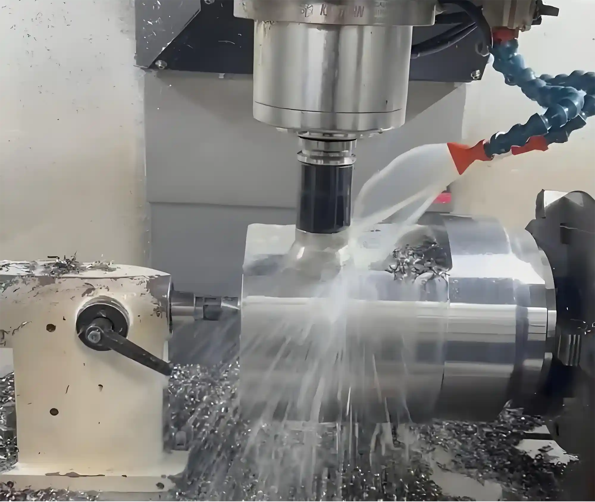
How to Calculate Cutting Speed, Cutting Volume, and Feed Rate for CNC Lathes
In CNC machining, 90% of dimensional errors, tool breakages, and wasted working hours often stem from one common issue: incorrect cutting parameters. Don’t underestimate those seemingly “simple” numbers—cutting speed, feed rate, and cutting depth. Behind these figures lie the fate of tool life, surface finish, and machining efficiency. A single mistake can lead to an increased scrap rate, halted production, and delayed deliveries. A scientific, precise, and practical parameter calculation method is the key weapon to improving yield and controlling costs.
Understanding these formulas will help you avoid most issues:
Cutting Speed: Vc = (π × D × N) ÷ 1000
Feed Rate: Vf = f × N
Feed per Revolution: f = Vf ÷ N
Depth of Cut: ap = (Initial D - Final D) ÷ 2
In the following sections, we’ll walk you step-by-step through detailed calculations, parameter tables, and a pitfall guide to help you systematically master core cutting parameters for CNC lathes—from formulas, to operations, to material matching.
I. What Do These Parameters Represent?

In CNC turning, cutting speed, cutting volume, and feed rate form an interrelated parameter system, each with critical functions:
1.Cutting Speed (Vc):
The relative linear speed at the contact point between the tool edge and the workpiece. It directly affects cutting efficiency and tool heat load.
Too low: prolonged machining cycle
Too high: increased tool wear or burning
2.Cutting Volume: Comprised of two key parameters:
Depth of Cut (ap): Indicates material thickness removed per pass; affects cutting force and efficiency.
Feed per Revolution (f): Distance the tool feeds per spindle revolution; core factor in surface roughness and cutting force distribution.
3.Feed Rate (Vf):
The tool's travel speed in the feed direction, determining material removal rate per unit time.
Too fast: poor surface finish
Too slow: low production efficiency
Proper coordination among these three delivers:
✅ Mirror-like surface finish (Ra value ↓ 30%+)
✅ Tool life ↑ 50%+
✅ Machining efficiency ↑ 40%
II. Calculation Formulas
1. Cutting Speed (Vc)
Formula:
Vc = (π × D × N) ÷ 1000
Where:
Vc: Cutting speed (m/min)
D: Workpiece diameter (mm)
N: Spindle speed (rpm)
2. Cutting Volume: Two Dimensions
(1) Depth of Cut (ap)
Formula:
ap = (Initial D - Final D) ÷ 2
(2) Feed per Revolution (f)
Formula:
f = Vf ÷ N
3. Feed Rate (Vf)
Formula:
Vf = f × N
III. Material-Based Parameter Guidelines
Metal Material Quick Reference Table
Material Type | Cutting Speed (m/min) | Depth of Cut (mm) | Feed per Revolution (mm/rev) |
45# Steel | 100–150 | 1–3 | 0.1–0.3 |
Aluminum Alloy | 300–600 | 2–5 | 0.2–0.5 |
Stainless 304 | 80–120 | 0.5–2 | 0.08–0.15 |
Machining Tips:
For stainless steel, use high feed + low speed to reduce built-up edge formation.
For aluminum alloys under high-speed cutting, use air cooling to prevent material softening and deformation.
Non-Metal Material Handling

Plastic Machining:
Use sharp PCD tools, Vc = 200–400 m/min
Feed ≤ 0.3 mm/rev to avoid burrs
Wood Machining:
Recommended Vc = 1500–3000 m/min (high RPM to prevent tearing)
For deep cuts (ap > 5mm), use multiple passes
IV. Common Pitfalls (Mistakes 90% of People Make)
1. Unit Conversion Errors
Typical Mistake:
Using inch-based diameter directly in the formula.
Solution:
Always convert:
D(mm) = D(inch) × 25.4
N(rpm) = (Vc × 1000) ÷ (π × D)
2. Ignoring Tool Material
Common Issue:
Using HSS tool with carbide tool parameters
Fix:
Reduce Vc by 50%
Reduce f by 30%
3. Lack of Coolant
Consequences:
No coolant during high-speed stainless cutting → tool life drops 80%
Countermeasures:
For steel: use water-soluble coolant (5–8% concentration)
For aluminum: use mineral oil-based cutting fluid
V. Calculation Aids
1. Online Calculators

Machinist Calculator:Supports metric/imperial switch, generates G-code from input.
2. Professional Software
Fusion 360:
Comes with built-in cutting parameter database; automatically optimizes Vc and f based on tool type.
3. Experience-Based Parameter Table
Material Hardness | Speed Correction Factor | Feed Correction Factor |
HRC 20–30 | 1.0 | 1.0 |
HRC 30–40 | 0.85 | 0.9 |
HRC 40–50 | 0.7 | 0.8 |
VI. Ultimate Operation Guide
1. First-Piece Trial Cut Principles:
Reduce spindle speed by 20%
Reduce feed by 30%
Set cutting depth to 50%
2. Abnormal Warning Signals:

Sudden spike in spindle current → possible overload
Shrill cutting sound → excessive feed
Blue chips → excessive heat
3. Tool Life Management:
Use the "80% life replacement rule"—e.g., if tool life is 10 hours, replace after 8 hours.
VIII. Conclusion
By mastering the logic behind these three core parameters and combining them with smart tools and field experience, you can significantly elevate precision and efficiency in CNC turning. Remember: parameter setting is a precise engineering task, grounded in material science and mechanical principles.
If you’re still unsure about how to set the right cutting speed, cutting volume, or feed rate during actual machining — or if you’re uncertain how to choose the optimal parameters for different materials, tools, or processes — feel free to contact the Minnuo engineering team. We’re here to offer you professional, practical, and free technical guidance!
(Note: The recommended parameters in this article are based on ISO standard machine tools; adjust as needed for your specific equipment.)


 Email
Email sales1: +86 13295238763

