



Precision Control for Large Mold Machining on Gantry Machining Centers: Vibration Damping & Deformation Prevention + Thermal Compensation Techniques
When machining large molds like automotive body panels on gantry machining centers, surface tolerance deviations (e.g., ±0.02mm) caused by chatter and thermal deformation, coupled with soaring scrap rates, represent core production challenges for mold manufacturers. This article addresses both issues by detailing a comprehensive practical solution—from clamping optimization and cutting parameter tuning to thermal compensation setup. It includes FANUC system parameter templates and clamping stress relief guidelines to help workshops stabilize surface tolerances within ±0.008mm while reducing scrap rates by 10%.
Are you puzzled by this: Despite using high-precision machines, large mold machining still suffers from chatter marks and thermal deformation causing tolerance overshoot? The root cause isn't insufficient machine precision, but rather vibrations from inadequate clamping rigidity and thermal deformation during continuous machining that hasn't been accurately compensated. These issues can be resolved without upgrading equipment—through targeted rigidity enhancements and thermal compensation optimization. This article outlines a practical implementation path designed to deliver these improvements.
More importantly, this article includes not only cutting parameter adjustment tables categorized by mold material and FANUC system thermal compensation parameter templates, but also a real-world case study of an automotive mold factory saving 22,000 yuan monthly in rework costs using this solution. A downloadable “Large Mold Clamping Stress Relief Guide” is also provided at the end. Continue reading to directly apply these tools and keep large mold precision risks within manageable limits.
I. Recognize the 3 Major Precision Pain Points in Large Mold Machining (with Actual Loss Data)
1. Chatter Causes Surface Roughness/Profile Deviation Exceeding Tolerances
Issue Manifestation: When machining automotive body panel molds, gantry ram vibration resulted in surface Ra ≥ 1.6μm and profile deviation exceeding 0.015mm.
Cost Impact: A automotive mold factory experienced a 12% monthly scrap rate due to chatter, with rework costs exceeding ¥25,000 per mold set;
Typical Scenario: Machining deep cavity surfaces with a 6:1 length-to-diameter ratio ball-nose cutter resulted in pronounced tool marks requiring manual polishing (8 hours/piece).
2. Thermal Deformation Causes Geometric Tolerance Failure
Issue Manifestation: Spindle temperature rises 8°C after 4 consecutive hours of machining, causing 0.012mm elongation; crossbeam deforms 0.015mm due to ambient temperature variation (5°C daily workshop temperature fluctuation), resulting in mold positioning tolerance exceeding 0.02mm;
Industry Pain Point: 70% of small-to-medium mold factories lack temperature-controlled workshops, with thermal deformation causing 40% of precision deviations.
Data Evidence: A factory processing large bumper molds suffered a 150,000 yuan loss due to customer returns caused by thermal deformation exceeding assembly tolerances.
3. Positioning Drift Due to Insufficient Clamping Rigidity
Issue Manifestation: Large molds (≥5 tons) secured only by clamping plates during setup. Cutting forces caused 0.008mm workpiece displacement during machining, directly exceeding surface tolerance limits.
Hidden Losses: Positioning drift necessitates re-alignment in subsequent processes, extending the machining cycle per mold by 2 days and increasing delivery delay risks.
II. Core Solution 1: Vibration Damping & Deformation Prevention — Rigidity Enhancement from Fixturing to Cutting
1. Fixturing Optimization: Dual Assurance of Rigidity Enhancement + Stress Relief
(1) Rigid Fixturing Implementation Template
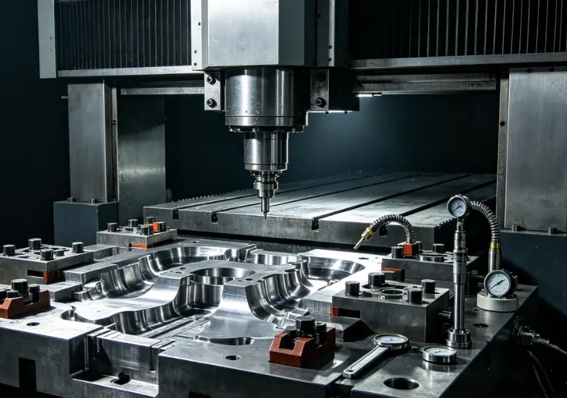
Fixture Selection: Hydraulic clamping system (clamping force ≥20kN/point) + auxiliary support pins (spacing ≤300mm, aligned with mold rib positions);
Operational Steps:
Before lifting the mold, clean the workbench reference surface (flatness ≤0.003mm);
Apply uniform clamping with hydraulic fixtures (torque ≥120N・m), using auxiliary support pins to brace vulnerable mold areas (e.g., edges, thin walls);
After clamping, verify mold flatness with a dial indicator (deviation ≤0.005mm) to prevent deformation from clamping stress.
(2) Stress Relief Techniques
After rough machining, idle for 2 hours to allow natural stress release (or accelerate release using vibration aging equipment, taking 30 minutes);
Re-inspect flatness before finishing. If deviation exceeds 0.003mm, fine-tune the fixture.
2. Cutting parameter adjustment: Scene-specific parameter table for chatter suppression
| Mold Materials | Processing Steps | Tool Type | Cutting Speed v_c (m/min) | Feed rate f (mm/rev) | Cutting depth a_p (mm) | Aspect Ratio Limit |
| P20 Mold Steel | Rough Machining | Corn Milling Cutter | 80–100 | 0.2–0.25 | 1.5–2.0 | ≤4:1 |
| 718 Mold Steel | Semi-Finish Machining | Bullnose R0.5 | 120–150 | 0.1–0.15 | 0.8–1.0 | ≤5:1 |
| S136 Mold Steel | Finish Machining | Ball Nose R3 | 180–220 | 0.05–0.08 | 0.2–0.3 | ≤3:1 |
Key Principles: Prioritize reducing feed rate (rather than cutting speed) during finishing to minimize chatter caused by cutting force fluctuations.
3. Tool and Spindle Adaptation: Reduce Vibration Transmission
Tool Selection: Use short-edged ball end mills (cutting length ≤ 15mm) for finishing to avoid the amplification effect of chatter from long-edged tools;
Tool Holder Selection: Use hydraulic tool holders (runout ≤ 0.002mm) instead of spring collets to enhance tool clamping rigidity;
Spindle Optimization: Enable spindle dynamic balancing (FANUC parameter 10370) to automatically compensate for dynamic balancing errors at speeds ≥ 8000rpm.
4. Machine Rigidity Optimization: Crossbeam + Ram Locking and Compensation
Crossbeam Locking: Enable automatic crossbeam locking (pressure ≥ 10MPa) before machining to prevent deformation of the crossbeam due to ram movement;
Ram Compensation: Set ram overhang compensation through machine parameters (FANUC 18500). For every 100mm increase in overhang length, compensate by 0.002mm.
III. Core Solution 2: Thermal Compensation Techniques – From Active Control to Passive Optimization
1. Root Cause Analysis of Thermal Deformation: 3 Major Heat Sources and Their Impact
Spindle Heat Source: Spindle motor heat causes spindle elongation (elongation ≈ 0.0015mm/100mm per 1℃ temperature rise);
Crossbeam Heat Source: Ambient temperature difference causes crossbeam thermal expansion and contraction (crossbeam length change ≈ 0.012mm/5m when the day-night temperature difference is 5℃);
Cutting Heat Source: Rough machining cutting heat causes localized temperature rise of 3-5℃ in the mold, leading to localized deformation.
2. Active Thermal Compensation: Precise System Parameter Settings (Compatible with FANUC / Siemens)
(1) FANUC System Thermal Compensation Parameter Template
Spindle Thermal Compensation: Parameters 18550 (Spindle elongation compensation coefficient, set to 0.0015), 18551 (Compensation trigger temperature threshold, set to 40℃);
Crossbeam Thermal Compensation: Parameters 18560 (Crossbeam temperature acquisition point setting), 18561 (Coefficient of thermal expansion, set to 11.5×10⁻⁶/℃);
Operation Steps: Use a laser interferometer to detect the thermal deformation data of the spindle/crossbeam, and substitute the parameters for automatic compensation.
(2) Siemens System Thermal Compensation Settings
Enable the “Thermal Compensation” function, import the real-time data collected by the temperature sensor, and the system automatically adjusts the coordinate axis position.
3. Passive Thermal Compensation: Cooling + Temperature Control in One Go
Spindle Cooling: Upgraded to a closed-loop oil cooling system (oil temperature fluctuation ≤ ±1℃) to prevent excessive spindle temperature rise;
Ambient Temperature Control: Air conditioning and insulation are installed in the workshop to control the day-night temperature difference within ±2℃ (in the absence of a constant temperature workshop, the machine can be stopped for 1 hour before finishing to allow it to cool down naturally);
Mold Cooling: High-pressure cold mist (pressure ≥ 0.8MPa) is applied to the cutting area during finishing to reduce local temperature rise in the mold.
4. Thermal Deformation Detection and Calibration: Periodic Accuracy Verification
Detection Tools: Laser interferometer (for detecting spindle/beam thermal deformation), ball bar (for detecting coordinate axis positioning accuracy);
Calibration Cycle: Once a month (once every two weeks during the high-temperature summer period), updating thermal compensation parameters based on the test results.
IV. Case Study: Precision Optimization at an Automotive Mold Factory
1. Original Problem
Equipment: MINNUO LM-5030 Gantry Machining Center (FANUC 31i System);
Machined Part: Automotive front bumper mold (dimensions 4800×1800mm, weight 6.5 tons);
Pain Points: Chatter caused surface Ra=2.0μm, thermal deformation caused contour deviation of 0.022mm, monthly scrap rate 12%.
2. Optimization Solution
Clamping Optimization: Hydraulic clamp + auxiliary support pins, vibration aging after rough machining to release stress;
Parameter Adjustment: R3 short-blade ball end mill (L/D ratio 3:1) for finishing, feed rate 0.06mm/rev;
Thermal Compensation: Set FANUC thermal compensation parameters, upgrade spindle closed-loop oil cooling system.
3. Optimization Results
Precision Improvement: Surface tolerance stabilized at ±0.007mm, Ra=0.8μm, meeting automotive mold standards;
Efficiency Improvement: Scrap rate decreased from 12% to 1.5%, and the processing cycle for a single mold was shortened by 2 days;
Cost Savings: Monthly rework costs decreased from 25,000 yuan to 3,000 yuan, resulting in annual savings of 264,000 yuan.
V. Common Precision Control Misconceptions and Avoidance Guidelines
1. Misconception 1: Adjusting Parameters Without Optimizing Clamping
Problem: Simply reducing the cutting speed does not improve precision because insufficient clamping rigidity still causes chatter;
Avoidance: Clamping optimization is fundamental. Solve the rigidity problem first, then adjust the parameters.
2. Misconception 2: Focusing on Spindle Thermal Compensation Only, Ignoring the Crossbeam
Problem: Compensating only for spindle thermal expansion does not prevent positioning deviations caused by crossbeam thermal deformation from exceeding 0.01mm;
Avoidance: Simultaneously enable spindle and crossbeam thermal compensation, and verify the overall effect using a laser interferometer.
3. Misconception 3: Excessive Tool Length-to-Diameter Ratio
Problem: Using a tool with a 6:1 length-to-diameter ratio to machine deep cavities causes chatter, making tool marks impossible to eliminate.
Avoidance: For finishing, use a tool with a length-to-diameter ratio ≤ 3:1. Use a five-axis linkage tilting tool for deep cavity areas (to reduce tool overhang).
4. Misconception 4: Ignoring Stress Release
Problem: Directly finishing after roughing leads to subsequent deformation and tolerance errors due to stress release issues in the mold.
Avoidance: Stress must be released after roughing, or a vibration aging device should be used to accelerate stress release.
VI. FAQ: Common Problems in Precision Control of Large Molds
Q: How to reduce thermal deformation in a workshop without a constant temperature environment?
A: Prioritize upgrading to a closed-loop oil cooling system for the spindle (cost 20,000-30,000 RMB). Before finishing, stop the machine for 1 hour to allow it to cool naturally. Simultaneously, use high-pressure cold mist to reduce local temperature rise in the mold. This can reduce thermal deformation errors by 30%.
Q: Can old gantry milling machines perform thermal compensation?
A: Yes! Older machine tools can be fitted with temperature sensors (costing less than 5000 RMB) and used with third-party thermal compensation software (such as Renishaw QC20-W) to achieve semi-closed-loop thermal compensation, improving accuracy by over 20%.
Q: How to quickly release clamping stress in large molds? A: Use vibration aging equipment (30 minutes per cycle, costing 15,000 RMB), which is 4 times more efficient than natural release and suitable for mass production scenarios.
Q: For surface tolerance requirements of ±0.005mm, is a higher precision machine tool necessary? A: Not necessarily! Through vibration damping and deformation prevention + thermal compensation optimization, ordinary gantry milling machines (positioning accuracy ±0.01mm) can also achieve a stable ±0.008mm; for higher precision, the MINNUO LM-6040 (positioning accuracy ±0.005mm) can be selected.
Conclusion
The core logic of precision control for large molds is "rigidity enhancement + thermal deformation compensation": chatter is suppressed through clamping optimization and parameter tuning, while temperature deformation is controlled through active/passive thermal compensation. The combination of these two approaches can stabilize surface tolerances within ±0.008mm, while simultaneously reducing scrap rates and rework costs. MINNUO gantry machining centers are designed with this logic in mind from the hardware stage: their standard automatic beam locking system (pressure ≥10MPa), ram overhang compensation function, and reserved interface for spindle closed-loop oil cooling provide a solid hardware foundation for rigidity enhancement and thermal compensation solutions, making precision optimization implementation more than 25% more efficient than ordinary machine tools.
Our compiled tools, such as the "Clamping Template" and "Thermal Compensation Parameter Guide," can assist in quickly advancing the solution. MINNUO customers can also obtain an additional brand-exclusive "Large Mold Precision Adaptation Manual." This manual is customized based on the specific parameters of MINNUO gantry milling machines (such as the thermal expansion coefficient of the crossbeam and the spindle temperature rise compensation coefficient), precisely aligning the operating steps in the toolkit with the actual working conditions of the equipment. For example, thermal compensation parameters can be directly imported into the MINNUO machine's FANUC system without repeated calibration, further reducing the trial-and-error costs and time required for solution implementation.
If you are currently optimizing the precision of large molds, you can start testing the chatter and thermal deformation data of the current molds today, and begin optimizing the clamping scheme and debugging the thermal compensation function this week. During this process, MINNUO's professional technical team can provide free precision diagnostic services, assisting you in completing the precision optimization of the first set of molds within one month, and achieving stable surface tolerances within ±0.008mm and a scrap rate below 2% for the entire workshop within three months. MINNUO will serve as a reliable support for improving mold machining precision, helping your workshop transform precision risks into stable production capacity and order revenue.
 Email
Email sales1: +86 15312799623