



Slant-Bed vs Flat-Bed CNC Lathes for Automotive Parts
For high-volume production of short shafts, bushings, hubs, and flanges, a slant-bed lathe is usually the first option to evaluate. A flat-bed CNC lathe is often more flexible for long shafts, prototypes, and high-mix, low-volume work. However, bed angle does not determine accuracy. The final decision should be based on thermal drift, continuous cutting trials, total cycle time, and cost per accepted part.
Why Automotive Buyers Should Not Select a Lathe by Bed Angle Alone
The claim that a slant-bed machine is inherently more advanced than a flat-bed machine is not a sufficient basis for procurement. Automotive purchasing managers must control production cycle time, process stability, process capability, and cost per accepted part.
Poor Chip Control Directly Reduces Unattended Production Time
Ductile iron chips, long low-carbon steel chips, and bulky aluminum chips behave differently. Chips accumulating around the chuck, turret, or way covers can cause:
- Chip recutting
- Scratches on finished surfaces
- Insert chipping or abnormal tool wear
- Chip conveyor, robot, or automatic-door alarms
- Shutdowns during unattended night shifts
A slant bed helps chips fall toward the conveyor under gravity, but it does not guarantee trouble-free chip evacuation. Insert geometry, feed rate, cutting depth, coolant direction, filtration, and conveyor design still determine the actual result.
Cutting Time Is Not the Same as Total Cycle Time
A complete production cycle also includes:
- Automatic-door movement
- Chuck clamping and unclamping
- Spindle acceleration and deceleration
- Turret indexing
- Bar feeder or robot loading
- In-process measurement
- Chip clearing and tool-offset updates
A supplier's net cutting time should not be used directly to calculate annual capacity.
Cold-Machine Accuracy Does Not Prove Thermal Stability
A conforming first-off part does not prove that diameter, roundness, cylindricity, and face runout will remain stable after four to eight hours of production. Acceptance testing must examine dimensional trends over time, not a single finished sample.
Cost per accepted part should be calculated over a consistent period:

Slant-Bed vs Flat-Bed Lathe: Eight Production-Capability Differences
| Comparison | Slant-bed lathe | Flat-bed CNC lathe | Procurement implication |
|---|---|---|---|
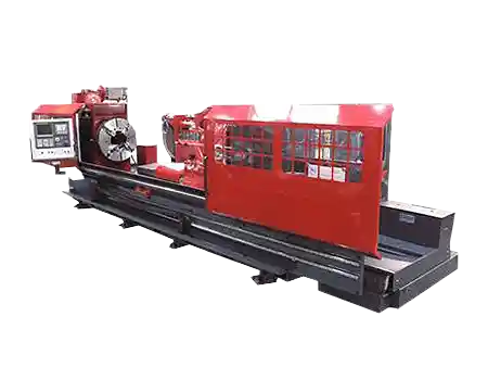
| Typical workpieces | Short shafts, bushings, gear blanks, hubs, and flanges | Long shafts, prototypes, repair parts, and low-volume large-diameter components | Classify by part family, length-to-diameter ratio, and annual volume |
| Chip path | Chips can fall more directly toward the conveyor | Chips are more likely to remain on horizontal bed surfaces and covers | Conduct continuous trials using the actual material |
| Automation | Commonly integrated with bar feeders, robots, sub-spindles, and automatic doors | Can be automated, but manual loading and tailstock work are more common | Compare the complete automated cycle |
| Long-part machining | Depends on bed length, tailstock, and steady-rest configuration | Long beds, tailstocks, and steady rests are often easier to arrange | Verify vibration and full-length cylindricity |
| Changeover and alignment | Suited to stable part families and repeat production | Often more convenient for high-mix work and manual alignment | Require a live changeover demonstration |
| Structural rigidity | A box-type slant bed and short force path can provide high rigidity | A wide flat bed with box ways can also support heavy cutting | Bed angle is not a rigidity rating |
| Accuracy retention | Depends on thermal design, guideways, ballscrews, assembly, and feedback | Depends on the same system-level factors | Review thermal-drift and test-piece reports |
| Main cost risk | Overconfigured automation and omitted peripheral interfaces | Manual chip clearing, non-cutting time, and limited unattended capability | Compare total lifecycle cost |
Haas identifies compact axis packaging, turret support, and chip evacuation as design advantages of its slant-bed construction. This is a manufacturer's description of its design, not a universal performance guarantee for every slant-bed lathe. Haas SB Series brochure
Four Published Machine Specifications: Use Consistent Capacity Definitions
Swing over bed describes the physical clearance above the bed. It is not the same as maximum machinable diameter. The following table separates maximum turning diameter, swing over bed, and swing over the cross slide to avoid a false ranking.
| Construction and model | Diameter definition | Length capacity | Spindle | Power and duty rating | X/Z rapid traverse |
|---|---|---|---|---|---|
| Slant bed: Okuma LB3000 EX III | Maximum machining diameter: 410 mm | Maximum machining length: 500 mm; 1,000 mm on specified configurations | 45-5,000 rpm | 22/15 kW, 30-minute/continuous | 25/30 m/min |
| Slant bed: Okuma LB4000 EX III | Maximum turning diameter: 480 mm | Current highlighted standard specification: 750 mm | 42-4,200 rpm; lower-speed large-bore options available | 30/22 kW; optional 37/30 kW | 30/30 m/min |
| Flat bed: KNUTH Numturn TC 500/1500 | Swing over bed: 508 mm; turning diameter over support: approximately 279 mm | Maximum turning length: approximately 1,245 mm | 35-2,500 rpm | 14.75 hp, approximately 11 kW continuous | 4/8 m/min |
| Flat bed: ROMI C 420 | Swing over bed: 430 mm; swing over cross slide: 200 mm | Distance between centers: 1,000 mm | A2-5: 4-4,000 rpm; A2-6: 3-3,000 rpm | 9 kW, S6-40% duty | 10/10 m/min |
Sources:
These machines serve different workpiece ranges and should not be ranked by one specification. The contract must also define the power duty rating, turret, spindle bore, chuck, tailstock, control, and optional equipment.
RFQ and Cutting-Trial Requirements for Three Automotive Part Families
Coolant pressure and micron-level acceptance limits should not be inferred from workpiece diameter. Suppliers should report actual data using the buyer's drawing, material, tooling, and production conditions.
| Part family | Configuration to evaluate | Mandatory RFQ data | Mandatory trial data |
|---|---|---|---|
| Short shafts, bushings, and bar-fed parts | Slant bed with bar feeder or robot | Spindle rpm and kW; complete cycle in seconds; bar capacity in mm; turret index time in seconds; coolant pressure in MPa and flow in m³/h | Short-term trend over 30 consecutive parts, offset frequency, tool life, chip accumulation, and alarms |
| Hubs, flanges, and gear blanks | Slant bed with robot and in-process gauging | Machining diameter in mm; chuck force in N; spindle torque in N·m; coolant and filtration data | Roundness, face runout, Ra, and critical dimensional deviations in μm, evaluated against the drawing |
| Long shafts, prototypes, and high-mix work | Flat bed or long-bed slant machine | Distance between centers in mm; tailstock thrust in N; steady-rest range in mm; changeover time in minutes | Full-length taper, cylindricity, chatter marks, alignment time, and operator interventions |
A 30-part run is useful for evaluating short-term repeatability, thermal trends, chip evacuation, and automation. It is not sufficient by itself to establish formal Cpk.
NIST notes that capability-index estimates generally require approximately 50 or more independent values. Process-stability studies should collect more than 100 observations over a sufficiently representative period. Automotive projects must also follow the customer's control plan, PPAP, and SPC requirements. NIST process capability guidance
Use two separate validation stages:
1.Machine cutting trial
Machine at least 30 consecutive parts to examine short-term dimensional trends, thermal drift, complete cycle time, chip control, and automation.
2.Process capability study
After demonstrating process stability and an acceptable measurement system, collect at least 100 observations, or the customer's specified subgroup data, before calculating Cp, Cpk, Pp, and Ppk.
A Coolant Specification Must Include More Than "High Pressure"
Required coolant pressure and flow depend on tool-orifice diameter, nozzle count, material, chip-breaking objective, and piping losses.
For example, the published Haas HPC-1000 specifications include:
- Maximum pressure: 1,000 psi, or approximately 6.89 MPa
- Maximum flow: 7 US gal/min, or approximately 26.5 L/min and 1.59 m³/h
- Actual flow varies with the tool-orifice size
These figures demonstrate why pressure and flow must be evaluated together. They do not mean every automotive part requires 6.89 MPa. Haas HPC-1000 operating information
The technical agreement should specify:
- The pressure-flow curve at the actual tool orifice
- Filtration rating and filter differential-pressure alarm
- Coolant-tank capacity
- Coolant-temperature rise during continuous operation
- Pump duty rating and power consumption
- Nozzle orientation and chip-evacuation results
Accuracy Acceptance: Bed Construction Cannot Replace ISO 13041 Data
The ISO 13041 series covers geometric accuracy, positioning, speeds and interpolation, finished test pieces, contouring performance, and thermal distortion.
ISO 13041-8 defines three thermal tests:
- Environmental temperature-variation error
- Thermal distortion caused by spindle rotation
- Thermal distortion caused by linear-axis movement
The standard applies to machine structures and positioning systems up to 2,000 mm in length. For longer travels, the buyer and supplier should define an extended test method in the contract. ISO 13041-8:2004
ISO 13041-6 defines finishing tests using standard test pieces to assess actual cutting accuracy. The 2009 edition remains current as of 2026. ISO 13041-6:2009
The purchase agreement should define:
- Ambient temperature and permitted variation
- Cold-machine reference condition and warm-up procedure
- Axis positioning and repeatability tests
- Spindle radial and axial runout
- X- and Z-axis thermal-drift curves
- Test-piece material, dimensions, tooling, and cutting parameters
- Roundness, cylindricity, face runout, dimensional deviation, and Ra
- Measurement equipment, resolution, calibration, and GR&R requirements
- Retest procedure and corrective-action responsibility
How to Verify Supplier Claims About Rigidity, Accuracy, and Chip Control
Published manufacturer specifications and ISO test methods can be verified. A specific machine's micron-level cutting performance cannot be assumed without an inspection report or controlled cutting trial.
What Do Published Specifications Actually Prove?
- The Okuma LB3000 EX III publishes a 410 mm maximum machining diameter, 5,000 rpm spindle speed, 22/15 kW power rating, and slant-box-bed construction.
- The KNUTH Numturn TC 500/1500 publishes a flat-bed design, approximately 1,245 mm maximum turning length, 2,500 rpm spindle speed, and approximately 11 kW continuous power.
- The ROMI C 420 publishes a 430 mm swing over bed, 200 mm swing over cross slide, 1,000 mm distance between centers, and 9 kW S6-40% power rating.
These specifications establish working range and rated capacity. They do not prove the final accuracy, cycle time, or tool life for the buyer's workpiece.
What Evidence Should Be Recorded During a Cutting Trial?
| Trial stage | Required record |
|---|---|
| Cold-machine first part | Critical dimensions, roundness, cylindricity, face runout, and Ra |
| Warm-up period | Critical dimensions every five parts or every 30 minutes |
| Stable operation | Spindle load, turret load, coolant temperature, and offset values |
| Chip-control test | Accumulation locations, conveyor current, cleaning frequency, and alarms |
| Automation test | Loading success rate, clamp confirmation, fault recovery, and complete cycle time |
| Final part | Same gauges, inspection program, and datum strategy used for the first part |
| Final report | Raw readings, trend charts, gauge identification, and calibration status |
A single precision sample, a positioning-accuracy value from a brochure, or a result obtained only after manual offset correction is not sufficient evidence of production stability.
Automotive Supplier Trial: What Does a Reduction from 103 to 34 Seconds Prove?
In a published Okuma automotive-component trial:
- The original single-turret process required 103 seconds.
- Sandvik tooling and Mastercam process changes reduced time and cost by approximately 33%.
- Adding simultaneous twin-turret machining reduced the cycle to 34 seconds.
- The supplier estimated annual savings of approximately USD 4 million.
View the original Okuma application report
Assume:
- Two shifts per day
- Eight hours per shift
- 250 working days per year
- 75% OEE
This provides 4,000 scheduled hours and 3,000 effective production hours per year.

| Calculation | 103-second process | 34-second process |
|---|---|---|
| Theoretical annual capacity | Approximately 104,854 parts | Approximately 317,647 parts |
| Net cycle hours per 100,000 parts | Approximately 2,861 hours | Approximately 944 hours |
| Scheduled hours at 75% OEE | Approximately 3,815 hours | Approximately 1,259 hours |
The results indicate:
- A cycle-time reduction of approximately 67.0%
- Theoretical capacity approximately 3.03 times the original capacity
- A theoretical annual increase of approximately 212,793 parts
Evidence boundary: This is a manufacturer-published collaborative trial and an annual savings estimate, not an independently audited 12-month operating report. The improvement resulted from tooling, CAM strategy, and simultaneous twin-turret machining. It cannot be attributed to slant-bed construction alone. Buyers must recalculate the return using their own volume, labor, tooling, scrap, and OEE data.
Frequently Asked Questions About Slant-Bed and Flat-Bed Lathes
Q: Is a slant-bed lathe always more accurate than a flat-bed lathe?
A: No. Accuracy depends on guideway and ballscrew assembly, spindle design, feedback systems, thermal compensation, workholding, tooling, and environmental conditions. Compare ISO 13041 test data and dimensional trends from a continuous cutting trial.
Q: Should high-volume automotive shafts be machined on a slant-bed or flat-bed lathe?
A: A slant-bed lathe with a bar feeder or robot is usually the first option to evaluate for short and medium-length shafts. A flat-bed machine may be more flexible for very long shafts, prototypes, high-mix work, or applications requiring frequent steady-rest adjustment. Decide using length-to-diameter ratio, complete cycle time, vibration trials, and cost per accepted part.
Q: How can a buyer verify the chip-control performance of a slant-bed lathe?
A:
- Use the actual production material and tooling.
- Run continuously for at least two to four hours.
- Record chip accumulation around the chuck, turret, and covers.
- Record conveyor current, manual cleaning, and alarm downtime.
- Check whether chips scratch finished surfaces.
- Repeat the test using roughing and finishing parameters.
Q: What accuracy and thermal-drift data should be recorded during acceptance?
A: Record axis positioning and repeatability, spindle radial and axial runout, test-piece dimensions, roundness, cylindricity, face runout, Ra, and X/Z thermal drift caused by spindle and linear-axis operation.
Q: Can 30 consecutive parts prove formal process capability?
A: No. Thirty parts can reveal short-term repeatability and thermal trends. A formal Cpk study requires a stable process, an acceptable measurement system, and data collected across representative time periods and subgroups. At least 100 observations are generally recommended unless the customer specifies another method.
Q: How should the cost per accepted part be calculated for slant-bed and flat-bed lathes?
A: Add depreciation, financing, labor, energy, tooling, coolant, maintenance, changeover, downtime, and scrap costs, then divide by accepted production. Use complete cycle time and actual OEE, not net cutting time.
 Email
Email sales1: +86 15312799623