



Surface Finish Explained: Roughness, Ra, Rz, Measurement, and Machining Methods
Surface finish is an important factor in manufacturing because it affects the appearance, dimensional fit, and functional performance of machined components. From automotive engine parts to aerospace components and precision molds, different applications require different surface characteristics.
Surface finish describes the condition of a manufactured surface, commonly evaluated through surface texture characteristics such as roughness, waviness, and lay. Roughness parameters such as Ra, Rz, and Rq help engineers measure and specify surface quality, while machining and finishing methods determine the surface texture that can be achieved.
However, a smoother surface is not always better. The appropriate surface finish depends on the component's function, material, operating conditions, and manufacturing requirements.
This guide explains what surface finish means, how roughness parameters are measured, how to interpret surface finish specifications, and how different machining processes influence the final surface quality.
1. What Is Surface Finish?
Surface finish refers to the condition and texture of a manufactured surface. In mechanical engineering, the term is often used to describe the small-scale irregularities remaining after machining or finishing operations.
These irregularities influence how a surface interacts with other components.
A surface may appear smooth to the naked eye while still containing microscopic peaks, valleys, and directional machining marks.
Surface finish is closely related to surface texture, which includes three main characteristics: roughness, waviness, and lay.
1.1 Surface Roughness
Surface roughness describes relatively fine, closely spaced irregularities on a surface.
These irregularities can result from cutting tool geometry, feed marks, abrasive action, material behavior, and other manufacturing conditions.
Roughness is commonly measured using parameters such as Ra, Rz, and Rq.
A lower roughness value generally indicates smaller measured surface height variations, but it does not automatically guarantee better functional performance.
1.2 Surface Waviness
Waviness refers to surface irregularities with larger spacing than those typically associated with roughness.
Waviness may be influenced by machine vibration, workpiece deflection, or variations in the manufacturing process.
For example, a machined surface may have a low Ra value but still contain unwanted waviness that affects dimensional fit or sealing performance.
1.3 Surface Lay
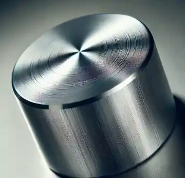
Lay describes the predominant direction or pattern of surface texture.
It is often associated with the direction of machining marks created by turning, milling, grinding, or other processes.
The direction of lay can influence sliding contact, lubrication behavior, and surface interaction.
Surface Finish vs. Surface Roughness
Although these terms are sometimes used interchangeably, they are not identical.
| Term | Meaning |
|---|---|
| Surface Finish | General description of the final surface condition |
| Surface Texture | Geometrical surface characteristics, including roughness, waviness, and lay |
| Surface Roughness | Fine-scale surface irregularities measured using defined parameters |
| Surface Finishing | Manufacturing or post-processing operations used to achieve or modify a surface condition |
Understanding these differences helps engineers specify the appropriate surface requirements rather than relying on visual appearance alone.
2. Surface Roughness Parameters: Ra, Rz, and Rq
Surface roughness parameters provide numerical measurements of surface texture.
Three commonly used profile parameters are Ra, Rz, and Rq.
These parameters describe different characteristics of the measured roughness profile and should not be treated as interchangeable.
2.1 Ra: Arithmetic Mean Roughness
Ra is one of the most widely used surface roughness parameters.
It represents the arithmetic mean of the absolute height deviations of the roughness profile from its mean line over the assessed length.
In practical terms, Ra describes the average magnitude of surface height variations.
For example, a surface specified as Ra 1.6 µm has a different roughness requirement from one specified as Ra 0.4 µm.
Under comparable measurement conditions, the lower Ra value indicates a smaller average roughness amplitude.
Advantages of Ra:
- Widely recognized in engineering drawings
- Useful for general machining quality control
- Convenient for comparing similar manufacturing processes
- Supported by most surface roughness measurement instruments
Limitations of Ra:
Ra alone does not describe the complete shape of a surface profile.
Two surfaces can have the same Ra value but different peak heights, valley depths, or directional textures.
Therefore, Ra may be insufficient when surface function depends on specific peaks, valleys, or contact characteristics.
2.2 Rz: Maximum Height of the Roughness Profile
Rz is a roughness parameter used to describe peak-to-valley height characteristics of the measured profile.
It is useful when larger surface irregularities may affect component performance.
However, Rz definitions and evaluation procedures have varied between measurement standards and historical conventions.
For example, the older ten-point height parameter, sometimes identified as RzJIS, is not identical to every ISO Rz definition.
Under the applicable ISO profile standard, Rz must be interpreted according to the specified parameter definition and measurement procedure.
Important: Ra and Rz cannot be converted into one another using a universal fixed ratio.
The relationship depends on the actual surface profile.
2.3 Rq: Root Mean Square Roughness
Rq represents the root mean square of the roughness profile height deviations from the mean line.
Because the calculation squares the height deviations before averaging, Rq gives greater weight to larger deviations than Ra.
This can make Rq useful when the distribution of surface heights is important.
However, Rq is not inherently more accurate than Ra. It simply describes the measured surface using a different mathematical parameter.
Comparison of Ra, Rz, and Rq
| Parameter | Description | Main Characteristic |
|---|---|---|
| Ra | Arithmetic mean roughness | Describes average absolute height deviations |
| Rz | Maximum height parameter defined by the applicable standard | Describes peak-to-valley height characteristics |
| Rq | Root mean square roughness | Gives greater weight to larger height deviations |
Which parameter should you use?
Ra is commonly suitable for general machining specifications.
Rz may be useful when peak-to-valley height is particularly relevant, while Rq can provide additional information about the distribution of surface deviations.
For demanding applications, engineers may also need parameters describing material ratio, valley structure, or three-dimensional surface texture.
The correct choice depends on the component's function and the applicable engineering standard.
3. How to Measure Surface Finish
Surface finish can be evaluated using contact and non-contact measurement methods.
The appropriate method depends on the surface geometry, required parameters, material properties, and measurement accuracy requirements.
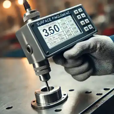
3.1 Contact Measurement: Stylus Profilometers
A contact profilometer uses a small stylus that moves across the surface.
As the stylus follows the surface profile, the instrument records height variations and calculates roughness parameters.
Common measurements include:
- Ra
- Rz
- Rq
- Other supported profile parameters
Advantages:
- Widely used in industrial inspection
- Suitable for many machined metal surfaces
- Provides standardized profile measurements
- Supports routine manufacturing quality control
Limitations:
- The stylus must physically contact the surface.
- Delicate surfaces may be vulnerable to contact damage.
- Stylus geometry can limit the measurement of very narrow valleys.
- Small features or difficult-to-access areas may require specialized instruments.
3.2 Non-Contact Measurement
Non-contact instruments use optical or other sensing techniques to evaluate surface geometry without physically tracing the surface with a stylus.
Common technologies include optical interferometry, confocal microscopy, and optical surface profiling.
Optical Interferometry
Optical interferometry uses light interference to measure surface height variations.
It is often used for precision surfaces where suitable optical measurement conditions are available.
Optical and Laser-Based Profiling
Optical surface measurement systems can capture surface height information across a profile or area.
They can be useful when inspecting complex textures or delicate components.
However, measurement performance depends on the instrument, surface reflectivity, material, optical resolution, and environmental conditions.
A non-contact instrument is not automatically more accurate than a contact profilometer for every application.
3.3 Two-Dimensional vs. Three-Dimensional Surface Measurement
Traditional profile measurements evaluate surface texture along a line.
Three-dimensional, or areal, measurement evaluates the surface over an area.
Common areal parameters include:
- Sa: Arithmetical mean height of a surface area
- Sq: Root mean square height of a surface area
These parameters are defined within the ISO 25178 series.
Areal measurement can provide additional information about surface texture distribution, particularly for surfaces with complex or nonuniform patterns.
However, profile and areal parameters should not be treated as directly interchangeable.
3.4 Important Surface Measurement Conditions
To obtain repeatable results, consider:
- Measurement direction relative to the surface lay
- Measurement location
- Sampling and evaluation lengths
- Appropriate filtering and specification settings
- Instrument calibration and verification
- Surface cleanliness
- The required number of measurements
For many directionally machined surfaces, measuring across the predominant lay is useful, subject to the applicable specification.
Surface roughness results should always be interpreted together with the measurement conditions and the specified standard.
4. Surface Finish Symbols and Standards
Surface finish requirements are commonly communicated through engineering drawings and technical specifications.
Standardized surface texture indications allow designers, manufacturers, and inspectors to use consistent requirements.
4.1 Understanding Surface Finish Symbols
Engineering drawings use graphical symbols to indicate surface texture requirements.
Depending on the applicable standard, the complete indication may communicate:
- Required roughness parameter and limit
- Surface manufacturing or material-removal conditions
- Direction of surface lay
- Additional measurement or specification information
For example, a drawing requirement involving Ra 1.6 µm identifies a roughness parameter and numerical value.
However, a complete engineering drawing specification may also require the appropriate surface texture symbol, standard, and other relevant conditions.
The designation should not be interpreted independently of the drawing's specified standard.
A roughness value alone does not identify the manufacturing method required to produce the surface.
4.2 ISO Surface Texture Standards
The following ISO standards are important for surface texture specification and measurement.
| Standard | Main Application |
|---|---|
| ISO 21920-1:2021 | Indication of profile surface texture requirements on technical drawings |
| ISO 21920-2:2021 | Profile surface texture terms, definitions, and parameters |
| ISO 21920-3:2021 | Specification operators for profile surface texture |
| ISO 25178-2:2021 | Areal surface texture terms and parameters, including Sa and Sq |
ISO 21920-1:2021 replaced ISO 1302:2002 for profile surface texture indications.
Older drawings may still reference ISO 1302 or earlier parameter definitions. In these cases, manufacturers should confirm which standard the drawing requires rather than automatically reinterpreting the specification under a newer standard.
For further information, refer to ISO 21920-1 and ISO 21920-2.
4.3 ASME Surface Texture Standards
In manufacturing environments using American engineering standards, relevant references include:
- ASME B46.1: Surface texture, including roughness, waviness, and lay
- ASME Y14.36: Surface texture symbols used on engineering drawings
ISO and ASME requirements should not be assumed to be identical in every detail.
When a supplier receives a surface finish specification, the drawing's applicable standard should be confirmed before machining or inspection.
5. Surface Finish by Machining Process
Different machining and finishing methods produce different surface textures.
The achievable roughness depends on material properties, machine stability, cutting tool condition, process parameters, and finishing requirements.
The following table provides approximate reference ranges for commonly used manufacturing processes.
Typical Surface Roughness by Manufacturing Process
| Manufacturing Process | Indicative Ra Range (µm) | Typical Application |
|---|---|---|
| Rough turning | 3.2–6.3 | Initial material removal on rotational components |
| Finish turning | 0.8–3.2 | Finished shafts, cylindrical surfaces, and other turned parts |
| Finish milling | 0.8–3.2 | Machined faces, pockets, and complex surfaces |
| Grinding | 0.2–0.8 | Precision surfaces and hardened components |
| Honing | 0.05–0.4 | Precision bores and internal cylindrical surfaces |
| Lapping | 0.025–0.2 | Precision mating surfaces and fine finishing |
| Polishing | 0.025–0.2 | Fine surface finishing and appearance improvement |
| Superfinishing | 0.01–0.1 | Selected high-precision contact surfaces |
Note: These are illustrative process ranges, not guaranteed capabilities or universal acceptance limits. Actual results can fall outside these ranges depending on the equipment, material, tooling, and process.
5.1 Turning and Milling
Turning and milling are widely used CNC machining operations.
Turning produces rotational surfaces using a cutting tool and a rotating workpiece.
Surface texture is influenced by feed rate, tool nose radius, cutting edge condition, workpiece material, and machine rigidity.
Milling produces flat, contoured, or complex surfaces using a rotating cutting tool.
Its surface finish depends on tool geometry, feed per tooth, spindle speed, step-over, toolpath strategy, and machine stability.
Both processes can achieve relatively fine finishes with suitable tooling and machining conditions.
5.2 Grinding
Grinding uses abrasive grains to remove small amounts of material from the workpiece surface.
It is commonly used for hardened materials and components requiring accurate geometry and fine surface texture.
Surface grinding and cylindrical grinding can produce low Ra values when the wheel specification, dressing condition, coolant delivery, and machining parameters are properly controlled.
However, poor grinding conditions can cause chatter, surface damage, or grinding burn.
5.3 Honing
Honing uses abrasive tools to improve the geometry and surface texture of a workpiece, commonly within cylindrical bores.
It is frequently used for applications requiring controlled internal surface characteristics.
For example, engine cylinder liners may require a specific surface texture that supports both sliding contact and lubricant retention.
In such applications, roughness parameters beyond Ra may be needed to describe the desired surface.
5.4 Lapping, Polishing, and Superfinishing
Lapping, polishing, and superfinishing can produce very fine surface textures.
Lapping uses abrasive action to refine surface geometry and texture, often for precision mating surfaces.
Polishing reduces or modifies surface irregularities through suitable finishing operations.
Superfinishing removes small amounts of material to refine the surface characteristics of selected precision components.
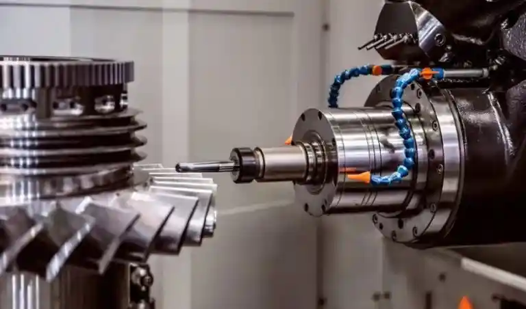
These processes can achieve fine finishes, but lower Ra values do not automatically mean better performance in every application.
The final finishing process should be selected according to functional requirements rather than appearance alone.
6. Factors Affecting Surface Finish and How to Improve It
Surface finish depends on the interaction between the material, cutting tool, machine tool, and machining conditions.
Understanding these factors helps manufacturers diagnose poor surface quality and select suitable improvements.
6.1 Workpiece Material Properties
Material hardness, ductility, microstructure, and thermal behavior influence the surface texture produced during machining.
For example, ductile materials may experience material smearing or built-up edge under unsuitable cutting conditions.
Hard materials may require specialized cutting tools or abrasive finishing processes.
Improvement: Select tooling and machining conditions appropriate for the specific material and its condition.
6.2 Cutting Tool Geometry and Condition
Cutting tool wear, edge geometry, and surface condition directly affect machining marks.
For turning operations, feed rate and tool nose geometry influence the theoretical profile left by the cutting edge.
Excessive tool wear may lead to tearing, rubbing, vibration, or inconsistent surface quality.
Improvement:
- Use suitable cutting tool geometry.
- Replace worn or damaged tools.
- Control tool overhang.
- Maintain stable toolholding.
- Select finishing tools appropriate for the required surface.
6.3 Cutting Parameters
Cutting speed, feed rate, and depth of cut influence cutting forces, heat generation, and surface formation.
Reducing feed rate may improve surface roughness in some finishing operations.
However, excessively low feed rates may cause rubbing or poor cutting behavior with certain tools and materials.
Improvement: Optimize machining parameters within the tool manufacturer's recommendations and verify results through actual measurements.
6.4 Machine Stability and Vibration
Machine tool vibration can produce unwanted surface marks and waviness.
Potential contributing factors include:
- Insufficient machine rigidity
- Worn spindle bearings
- Poor toolholding
- Excessive tool overhang
- Unstable workholding
- Improper cutting parameters
Improvement: Check machine condition, eliminate avoidable vibration, and maintain adequate tool and workpiece support.
6.5 Coolant and Lubrication
Cutting fluids can influence surface quality by providing cooling, lubrication, and chip removal.
Inadequate coolant application may increase friction, tool wear, or material adhesion.
Improvement: Use suitable coolant or lubrication methods according to the cutting process, material, and tooling requirements.
6.6 Practical Surface Finish Improvement Checklist
When the measured roughness exceeds the required limit:
- Confirm the measurement method and drawing specification.
- Inspect the cutting tool or grinding wheel condition.
- Check the workpiece material and machining parameters.
- Evaluate toolholding, workholding, and machine vibration.
- Review coolant application and chip removal.
- Perform a controlled finishing test.
- Measure the surface again under consistent conditions.
The objective is to achieve the specified surface quality consistently without introducing unnecessary machining time or finishing costs.
7. How Surface Finish Affects Component Performance
Surface finish is important because it influences how a component functions in its intended application.
However, the relationship between surface roughness and performance depends on the operating conditions.
7.1 Friction, Wear, and Lubrication
Surface texture influences the contact between moving components.
Excessively rough surfaces may create unfavorable contact conditions, increase wear, or affect friction.
However, some lubricated surfaces benefit from controlled valleys that help retain lubricant.
Therefore, the lowest possible Ra value is not always the best choice.
7.2 Fatigue Performance
Surface texture can influence fatigue behavior, particularly when roughness peaks, machining marks, scratches, or other surface features act as stress concentration sites.
The effect depends on material properties, loading conditions, residual stress, and surface integrity.
Improving surface finish may be beneficial, but Ra alone cannot fully predict fatigue life.
7.3 Sealing and Dimensional Fit
Surfaces used for sealing or precision mating may require controlled roughness and waviness.
A surface can meet an Ra requirement while still containing local defects or waviness that interfere with sealing.
For critical sealing applications, additional specifications may therefore be necessary.
7.4 Surface Finish Requirements by Industry
Different industries prioritize different surface characteristics.
| Industry | Typical Components | Important Surface Considerations |
|---|---|---|
| Aerospace | Shafts, structural components, turbine-related parts | Surface integrity, fatigue performance, geometry, and finish |
| Automotive | Bearing journals, engine components, cylinder bores | Wear resistance, lubricant retention, and dimensional fit |
| Medical Devices | Instruments and implants | Material compatibility, cleanliness, surface texture, and applicable regulatory requirements |
| Mold Manufacturing | Mold cavities and precision inserts | Surface texture, appearance, release behavior, and dimensional accuracy |
| Electronics and Precision Engineering | Precision housings and mating components | Contact characteristics, fit, and controlled surface texture |
Surface roughness alone does not determine the performance of these components.
For example, medical implant performance depends on material, surface chemistry, biological response, manufacturing quality, and other factors. A specific Ra value cannot independently establish improved clinical outcomes.
7.5 How to Choose the Right Surface Finish
When selecting a surface finish requirement, consider the following questions:
What is the function of the surface?
Determine whether the priority is sliding contact, sealing, dimensional fit, appearance, or another requirement.
Which surface parameters are important?
Ra may be sufficient for general inspection, while functional surfaces may require Rz, other profile parameters, or areal surface texture measurements.
Which manufacturing process can achieve the requirement?
Evaluate turning, milling, grinding, honing, lapping, or polishing according to the material, geometry, tolerance, and production cost.
How will the surface be inspected?
Specify or confirm the measurement standard, required parameters, and inspection conditions.
Can the requirement be achieved consistently?
A surface finish specification should be technically appropriate and economically reasonable for the intended production process.
The best surface finish is the one that meets the component's functional requirements—not necessarily the smoothest finish that can be manufactured.
Conclusion
Surface finish plays an important role in manufacturing quality, component performance, and product reliability.
Understanding roughness, waviness, and lay provides the foundation for evaluating surface texture.
Parameters such as Ra, Rz, and Rq allow engineers to quantify different aspects of surface roughness, while contact and non-contact measurement methods help verify manufacturing results.
Different machining processes—including turning, milling, grinding, honing, polishing, and superfinishing—offer different surface finishing capabilities.
To achieve reliable results, manufacturers should:
- Understand the required surface texture parameters.
- Follow the applicable engineering drawing standards.
- Select machining and finishing methods appropriate for the material and component.
- Optimize tooling, cutting parameters, and machine stability.
- Verify the finished surface using suitable measurement procedures.
Achieving the correct surface finish means balancing functional performance, manufacturing capability, inspection requirements, and production cost.
For more information about CNC machining equipment and manufacturing applications, contact MINNUO to discuss your machining requirements.
Frequently Asked Questions (FAQ)
Q1. What is the difference between surface finish and surface roughness?
A:Surface finish is a general term describing the final condition of a manufactured surface. Surface roughness refers specifically to fine-scale surface irregularities measured using defined parameters.
Q2. What is the difference between Ra and Rz?
A:Ra describes the arithmetic mean of the absolute roughness profile deviations, while Rz describes maximum-height characteristics according to the applicable measurement standard.
The two parameters provide different information and cannot be converted using a universal ratio.
Q3. Is a lower Ra value always better?
A:No. A lower Ra value generally indicates smaller average height variations, but the best surface texture depends on the application.
Some surfaces require controlled texture for lubrication, sealing, or other functional purposes.
Q4. Which machining process produces the smoothest surface finish?
A:Processes such as lapping, polishing, and superfinishing can produce very fine surface textures.
However, actual roughness depends on material, equipment, tooling, and process conditions. No single process guarantees the best finish for every component.
Q5. How is surface finish measured?
A:Surface finish can be measured using contact profilometers or suitable non-contact optical instruments.
The measurement method should match the specified parameters, component geometry, and applicable standards.
Q6. Which standards are used for surface finish specifications?
A:Common references include ISO 21920 for profile surface texture, ISO 25178 for areal surface texture, ASME B46.1 for surface texture, and ASME Y14.36 for drawing symbols.
The applicable standard should be identified before manufacturing or inspecting the component.
 Email
 sales1: +86 15312799623