



CNC Vertical Machining Centers for Automotive Parts: Applications & Selection Guide
CNC vertical machining centers are widely used to machine automotive brackets, electric vehicle (EV) motor housing features, transmission case surfaces, hydraulic valve bodies, and precision manufacturing fixtures. They are particularly suitable for components requiring accessible milling, drilling, boring, and tapping operations.
However, not every automotive component is suitable for a conventional three-axis vertical machining center. The right equipment depends on workpiece geometry, material properties, machining accessibility, dimensional tolerances, and production volume.
For example, a compact aluminum mounting bracket may be machined efficiently in a single setup, while a transmission housing with precision bores on several faces may require additional setups, rotary-axis equipment, or a horizontal machining center.
This guide explains where CNC vertical machining centers are used in automotive production, how different components affect machine selection, and which technical factors manufacturers should evaluate before investing in equipment.
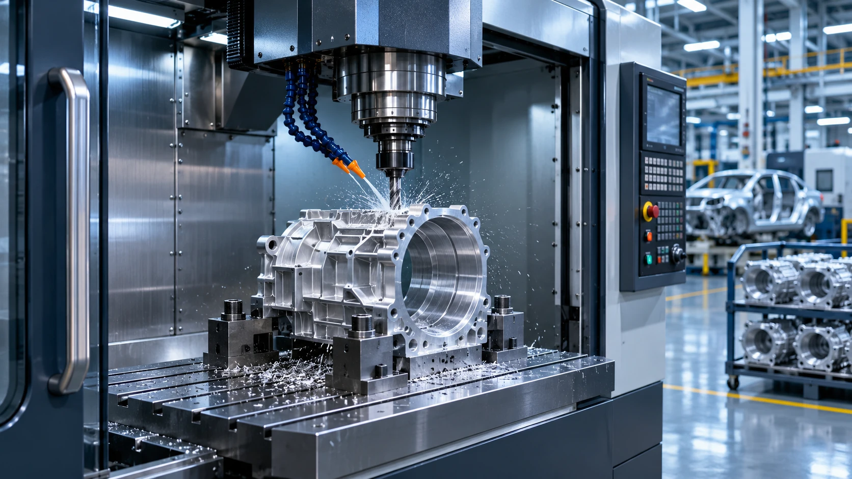
1. What Automotive Parts Can a CNC Vertical Machining Center Machine?
A CNC vertical machining center (VMC) is a milling machine with a vertically oriented spindle and computer-controlled axis movements. Equipped with an automatic tool changer, it can perform several machining operations without requiring the operator to transfer the workpiece between different machines.
This versatility makes VMCs useful in both conventional automotive manufacturing and EV component production.
Common Automotive Components and CNC Machining Operations
| Automotive component | Typical machining operations | Key manufacturing requirements |
|---|---|---|
| EV motor housings | Face milling, drilling, tapping, accessible bore machining | Bearing seat geometry, alignment, dimensional stability |
| Transmission and gearbox housings | Face milling, boring, drilling, tapping | Bore positioning, datum consistency, sealing surfaces |
| Automotive mounting brackets | Face milling, pocket milling, drilling, tapping | Hole position, dimensional consistency, cycle time |
| Hydraulic valve bodies | Drilling, reaming, tapping, surface milling | Bore quality, burr removal, internal cleanliness |
| Battery system mounting components | Face milling, drilling, contour milling | Flatness, hole positioning, deformation control |
| Suspension mounting components | Milling, drilling, boring | Geometric tolerances, material-specific cutting performance |
| Automotive molds and fixtures | Rough milling, finish milling, drilling, tapping | Dimensional stability, surface finish, repeatability |
These components have very different manufacturing requirements.
A simple bracket may require only face milling and drilling, while a gearbox housing may involve several precision bores, different machining orientations, and demanding geometric tolerances.
Understanding these differences is the first step toward choosing the right machining center.
When Is a 3-Axis Vertical Machining Center the Right Choice?
A three-axis VMC is generally suitable when the primary machining features can be accessed along the vertical spindle direction.
It is commonly used for components with accessible flat surfaces, pockets, slots, mounting holes, and other features that can be machined from above.
Its main advantages include flexible programming, automatic tool changing, straightforward workholding for many part geometries, and the ability to combine several cutting operations in one setup.
However, three-axis machining has limitations.
Components with undercuts, angled features, or precision holes on multiple sides may require additional positioning operations.
In these cases, a fourth-axis rotary table, a five-axis machining center, or a horizontal machining center may be more appropriate.
The key selection principle is machining accessibility, not simply the number of axes or the overall machine size.
2. EV Motor Housing Machining: Processes, Accuracy, and Machine Requirements
Electric motor housings provide structural support and mounting interfaces for components within an EV drivetrain.
Depending on the design, they may contain bearing seats, mounting surfaces, threaded holes, sealing interfaces, and structural pockets.
Aluminum alloy castings are commonly used because they offer a useful combination of low weight, thermal conductivity, and manufacturing flexibility.
However, achieving consistent dimensional accuracy can be challenging, especially when the housing contains relatively thin sections.
What Motor Housing Features Can a 3-Axis VMC Machine?
A three-axis vertical machining center can machine accessible motor housing features, including:
- Motor mounting and locating surfaces.
- Threaded assembly holes.
- Accessible bearing seats.
- Sealing interfaces.
- Structural pockets and clearance features.
- Connection and positioning surfaces.
Combining several operations within one setup can reduce handling and minimize unnecessary datum transfers.
However, some motor housings contain critical features on opposite ends.
If the required bearing bores cannot be reached from the same machining direction, additional setups or rotary-axis equipment may be necessary.
The machining process must be developed around the specific drawing rather than assuming that all housing features can be completed with a standard three-axis arrangement.
How Do Clamping and Thermal Deformation Affect Bearing Bore Accuracy?
Thin-walled aluminum housings can deform under clamping pressure.
For example, a fixture may temporarily distort the housing during machining. After the clamps are released, the component may recover elastically, changing the measured dimensions or geometry.
Other factors include casting residual stresses, uneven material removal, cutting forces, tool deflection, and temperature variation.
These effects become particularly important when the drawing specifies demanding requirements for bearing seat diameter, roundness, position, or alignment.
Engineers should focus on three areas.
Workholding stability
Locate the component using appropriate datums and support regions with sufficient rigidity. Avoid excessive clamping pressure on unsupported thin walls.
Machining sequence
Plan roughing and finishing operations to control material removal. For distortion-sensitive parts, intermediate inspection may be necessary before final precision machining.
Measurement strategy
Inspect critical features using the specified datum reference frame and measurement conditions. Where clamping distortion is suspected, compare relevant measurements before and after fixture release.
The final machining process should demonstrate that the component remains within tolerance under its required inspection conditions.
How to Choose a VMC for Aluminum EV Motor Housings
Machine selection should consider:
- Housing dimensions and fixture requirements.
- Available X/Y/Z travel.
- Spindle-to-table clearance.
- Cutting tool reach and stiffness.
- Available spindle power and torque.
- Coolant delivery and chip evacuation.
- Thermal stability.
- Required geometric accuracy.
A larger machining envelope may be necessary for some housings, but additional travel does not automatically provide better bearing bore accuracy.
The complete machine, fixture, tooling, and inspection process must be evaluated together.
3. CNC Machining of Automotive Transmission Cases and Gearbox Housings
Automotive transmission cases and electric-drive gearbox housings contain multiple machined features that support shafts, bearings, gears, and connecting components.
Their production often requires accurate relationships between several bores, mounting surfaces, and locating features.
Common Milling, Drilling, and Boring Operations
Typical operations include:
- Milling mating and sealing surfaces.
- Machining mounting and locating features.
- Rough and finish boring of accessible bearing seats.
- Drilling lubrication passages.
- Tapping assembly holes.
- Milling accessible pockets and recesses.
Some of these operations are well suited to vertical machining centers.
However, the complete process depends on how the features are distributed around the housing.
How to Maintain Bore Alignment Across Multiple Setups
Transmission cases may contain bearing bores that must maintain specified positional or coaxial relationships.
When these bores are machined in different setups, datum transfer becomes a critical part of process planning.
Potential sources of variation include fixture positioning, clamping deformation, tool deflection, machine geometry, and temperature changes.
Engineers should evaluate whether related precision features can be completed within one setup.
When multiple setups are unavoidable, the fixture system must provide repeatable location and sufficient stability.
Inspection should verify the geometric relationships specified by the drawing, rather than relying only on individual hole diameters.
For high-volume production, process capability studies may also be appropriate once a stable process has been established.
When Does Transmission Case Machining Require a Horizontal Machining Center?
A horizontal machining center may offer advantages when a housing requires extensive machining on several sides.
Depending on its configuration, an HMC can support indexed multi-face machining and reduce the need for manual repositioning.
Its horizontal spindle arrangement may also improve chip evacuation from certain cavities.
However, an HMC is not automatically the best solution for every gearbox component.
A VMC may remain practical for machining accessible mating surfaces, mounting holes, and selected bearing seats.
The decision should consider the complete manufacturing cycle, fixture complexity, tooling, required tolerances, and total cost per qualified component.
4. CNC Vertical Machining Centers for Automotive Brackets and Mounting Parts
Automotive brackets, mounting plates, and support components are among the most practical applications for vertical machining centers.
They are used in engine compartments, electric drive systems, suspension assemblies, and structural connections.
Many have relatively accessible geometries and require several milling and drilling operations.
Typical Milling, Drilling, and Tapping Operations
Common machining operations include:
- Face milling to establish reference surfaces.
- Pocket milling for clearance or weight reduction.
- Slot milling for mounting features.
- Drilling assembly holes.
- Tapping threaded connections.
- Contour milling to finish external profiles.
A VMC can often complete several of these operations during the same setup.
For manufacturers handling different bracket designs, flexible CNC programming and automatic tool changing can simplify production scheduling.
Aluminum vs. Steel Brackets: Cutting Speed, Torque, and Tool Wear
Material selection has a direct effect on machining strategy.
| Material | Main machining considerations |
|---|---|
| Aluminum alloys | Chip evacuation, built-up edge, surface finish, cutting speed |
| Carbon steel | Cutting forces, tool wear, spindle torque, heat generation |
| Cast iron | Abrasive wear, chip and dust management, cutting stability |
| Stainless steel | Work hardening, heat concentration, tool life |
Aluminum may allow higher cutting speeds under suitable conditions, while steel roughing can place greater demands on spindle torque and machine rigidity.
Tool geometry, coating, coolant strategy, and cutting parameters should be selected for the specific material.
There is no single spindle speed or feed rate suitable for every automotive bracket.
Choosing a Compact VMC for Automotive Bracket Production
For compact brackets, the machine should provide enough travel for the complete toolpath and sufficient worktable capacity for the fixture and workpiece.
The automatic tool changer should accommodate the required cutting tools without unnecessary manual intervention.
However, a larger machine does not automatically improve productivity.
If a smaller machine can complete the part at the required quality and cycle time, it may provide a more economical solution.
The decision should be based on the actual part geometry, machining sequence, cutting loads, and available production time.
5. Hydraulic Valve Body Machining: Hole Accuracy, Burrs, and Cleanliness
Hydraulic valve bodies and fluid-control components contain machined passages, precision bores, threaded connections, and sealing surfaces.
Their quality depends on more than dimensional accuracy.
Internal burrs, residual chips, and surface defects may affect component assembly or fluid-control performance.
Typical Drilling, Reaming, and Tapping Operations
Vertical machining centers can perform operations such as drilling fluid passages, reaming precision holes, tapping threaded connections, and milling accessible sealing surfaces.
The machining process depends on the component's geometry and functional requirements.
For valve bodies containing multiple intersecting passages, engineers must evaluate how each feature will be accessed and how the resulting burrs will be removed.
Some components may require multiple setups or specialized machining arrangements.
How to Control Burrs in Intersecting Holes
Burrs can form when a cutting tool exits a surface or intersects an existing passage.
Their formation depends on several factors, including:
- Workpiece material.
- Cutting tool geometry.
- Tool wear.
- Cutting parameters.
- Hole machining sequence.
- Support conditions around the exit surface.
Optimizing these factors can help reduce burr formation.
However, machining adjustments alone may not eliminate every burr.
Depending on the component requirements, dedicated deburring operations may be necessary.
These can involve mechanical, abrasive, thermal, or other processes appropriate for the material and passage geometry.
Inspection and Cleaning Requirements for Hydraulic Components
A valve body may meet its dimensional tolerances while failing cleanliness or functional requirements.
Manufacturers should therefore evaluate:
- Hole dimensions and geometric tolerances.
- Burr removal.
- Internal passage cleanliness.
- Residual particle levels.
- Thread condition.
- Sealing surface quality.
- Applicable leakage and functional tests.
Acceptance criteria should follow the drawing, cleanliness specification, and customer quality requirements.
Successful valve body manufacturing requires an integrated approach to machining, deburring, cleaning, and inspection.
6. CNC Machining Applications for EV Battery Components and Fixtures
EV battery manufacturing uses multiple production methods, including casting, extrusion, stamping, welding, machining, and assembly.
Vertical machining centers are particularly useful when selected components require precision-machined mounting or locating features.
They are also used to manufacture production fixtures and inspection equipment.
Battery Housing Interfaces and Structural Mounting Parts
Suitable operations may include:
- Milling mounting surfaces.
- Drilling assembly holes.
- Tapping threaded interfaces.
- Machining locating features.
- Finishing structural connectors.
- Preparing accessible sealing interfaces.
The complete manufacturing method depends on the size, material, and construction of the battery component.
CNC Machining of Battery Assembly and Inspection Fixtures
Battery assembly lines often require accurately manufactured fixtures.
Examples include locating plates, mounting brackets, inspection fixture bases, positioning blocks, and precision support components.
For these applications, repeatable workholding and geometric accuracy are important.
The machine should be selected according to the fixture dimensions, cutting requirements, and specified tolerances.
When Is a Conventional VMC Unsuitable for Large Battery Housings?
Large battery enclosures may exceed the machining travel or table capacity of conventional VMCs.
Even when the workpiece fits physically on the machine, the complete toolpath may require additional space.
Long or thin components can also be sensitive to clamping deformation and vibration.
Such applications may require specialized fixtures, larger machining centers, or alternative production methods.
7. How to Choose a CNC Vertical Machining Center for Automotive Production
Selecting a VMC should begin with the workpiece drawing, machining process, and expected production volume.
The following factors have the greatest influence on equipment suitability.
Machine Travel and Worktable Size: How Much Capacity Do You Need?
Machine travel does not directly equal the maximum workpiece dimensions that can be fully machined.
Engineers should evaluate:
- Complete tool-center movement.
- Fixture and clamp positions.
- Tool approach and retraction distances.
- Spindle-to-table clearance.
- Toolholder dimensions.
- Potential collisions.
- Combined workpiece and fixture weight.
For example, a component measuring 600 mm in length does not automatically fit every machining process on a machine with 650 mm X-axis travel.
Additional travel may be required for cutter radius, entry and exit movements, or other operations.
Spindle Speed vs. Torque: What Matters for Aluminum and Steel?
The relationship between cutting speed and spindle speed is:
n=1000Vc÷π·D
Where:
- (n) = spindle speed (rpm)
- (Vc) = cutting speed (m/min)
- (D) = cutting tool diameter (mm)
Suppose a 10 mm cutter operates at an assumed cutting speed of 200 m/min.
n=1000×200÷π·10≈6366rpm
An 8,000 rpm spindle can meet this theoretical speed requirement.
However, 200 m/min is only a calculation example, not a universal cutting recommendation.
Actual cutting conditions should be based on the material, cutting tool specifications, and process testing.
For larger-diameter tools or heavier roughing operations, spindle torque and available power at the operating speed may be more important than maximum spindle speed.
Positioning Accuracy vs. Finished-Part Accuracy
Machine positioning accuracy and finished-part accuracy are different concepts.
Machine axis accuracy describes positioning performance under defined measurement conditions.
Finished-part accuracy is also affected by:
- Machine geometric errors.
- Cutting tool deflection.
- Thermal expansion.
- Workpiece deformation.
- Tool wear.
- Cutting forces and vibration.
- Measurement uncertainty.
Research published by the National Institute of Standards and Technology (NIST) discusses machine tool calibration, including intra-axis, inter-axis, and volumetric errors.
This highlights why machine specifications alone cannot guarantee the accuracy of a finished automotive component.
For machine acceptance, applicable standards may include ISO 230-2 and relevant parts of the ISO 10791 series.
The specific testing standard and acceptance conditions should be established in the technical agreement.
Reference: NIST — Machine Tool Calibration
Workholding, Thermal Stability, and Tool Deflection
Workholding should provide stable support without causing unacceptable deformation.
For thin-walled components, the position and distribution of clamping forces can significantly affect dimensional results.
Tool deflection is another important consideration, particularly when long tools are required for deep pockets or bores.
Thermal stability also affects precision machining.
Temperature changes in the machine structure, spindle, workpiece, and surrounding environment may contribute to dimensional variation.
Manufacturers should evaluate these factors when developing processes for long production runs.
Tool Magazine Capacity, Coolant, and Automation Options
Automatic tool changers allow several machining operations to be completed without manual tool replacement between each operation.
However, tool magazine capacity should reflect the actual tool list rather than an arbitrary preference for more tools.
Other equipment considerations include:
- Tool change time.
- Maximum tool length and weight.
- Tool-life monitoring.
- Workpiece probing.
- Tool measurement systems.
- Coolant delivery.
- Chip evacuation.
- Automatic loading and unloading.
Automation may reduce handling time, but its economic value depends on cycle time, production volume, equipment investment, and integration requirements.
Example: Matching Machine Capacity to Workpiece Size
A practical way to begin equipment selection is to compare the workpiece and fixture requirements with the available machining envelope.
For instance, the MN CNC VMC650 offers 650 × 400 × 500 mm X/Y/Z travel, while the VMC1160 provides 1,100 × 600 × 600 mm.
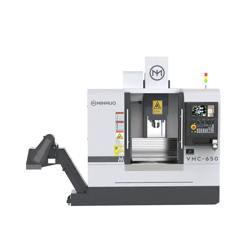
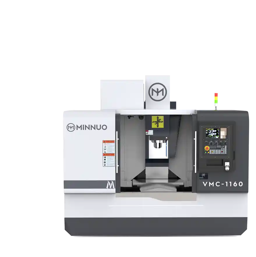
The smaller machining envelope may be sufficient for compact brackets, mounting plates, and certain valve components. Larger housings and fixtures may require additional travel and worktable capacity.
These published dimensions illustrate the importance of matching machine capacity to the workpiece. They do not independently establish that either model can meet a particular automotive tolerance or production target.
8. CNC Machining Cycle Time and Production Capacity Calculation
Automotive manufacturers need to evaluate not only whether a machine can produce a component, but also how many qualified parts it can deliver within the available production time.
What Determines Cycle Time in Automotive CNC Machining?
A complete machine cycle may include:
- Cutting operations.
- Rapid positioning movements.
- Automatic tool changes.
- Workpiece loading and unloading.
- In-machine measurement.
- Other machine-occupying operations.
Some automated activities can overlap with machining, while others cannot.
Cycle-time calculations should avoid counting overlapping activities twice.
How to Calculate the Number of CNC Machines Required
An initial equipment requirement can be estimated using:
N=Q×T÷60HY
Where:
- (N) = estimated number of machines.
- (Q) = annual target of qualified parts.
- (T) = complete machine cycle time in minutes.
- (H) = annual effective production hours per machine.
- (Y) = expected qualified yield as a decimal.
Example: Planning Annual Capacity for 60,000 EV Motor Housings
Assume the following hypothetical production conditions:
| Production parameter | Assumed value |
|---|---|
| Annual qualified parts target | 60,000 |
| Machining time | 6 min/part |
| Loading and machine-side measurement | 2 min/part |
| Complete machine cycle | 8 min/part |
| Annual effective production time | 1,800 h/machine |
| Expected qualified yield | 95% |
The theoretical processed quantity per machine is:
1800×60÷8=13500
After accounting for the assumed yield:
13500×0.95=12825
The estimated machine requirement is:
N=60000÷12825≈4.68
Therefore, five machines would be the initial planning quantity under these assumptions.
Their estimated annual qualified output would be:
5×12825=64125
This is approximately 6.9% above the annual target.
Why Machine Availability and Production Reserve Matter
The calculation assumes 1,800 hours of genuinely effective production time per machine.
If 1,800 hours represents scheduled working time rather than effective operating time, additional losses must be considered.
These may include maintenance, equipment downtime, tool replacement, setup changes, and production interruptions.
Losses already included in the effective hours or yield assumptions should not be counted again.
The five-machine result is therefore a preliminary estimate rather than a guaranteed production requirement.
A final capacity plan should use validated cycle times, realistic equipment availability, expected yield, and an appropriate capacity reserve.
This example is a hypothetical engineering calculation, not an actual customer production result.
9. Vertical vs. Horizontal Machining Centers for Automotive Parts
Both vertical and horizontal machining centers are used in automotive manufacturing.
Their suitability depends on workpiece geometry, feature accessibility, machining sequence, and production volume.
Differences in Machining Accessibility and Workholding
| Comparison | Vertical machining center | Horizontal machining center |
|---|---|---|
| Spindle orientation | Vertical | Horizontal |
| Typical applications | Brackets, plates, accessible housing features | Multi-face housings and box-type components |
| Workpiece accessibility | Convenient for top-facing operations | Often advantageous for side-facing operations |
| Multi-face machining | May require rotary attachments or multiple setups | Can support indexed multi-face machining |
| Chip evacuation | Depends on geometry and coolant system | May offer advantages for some cavities |
| Workholding | Often straightforward for accessible components | Can support multi-face fixtures and pallet systems |
| Production flexibility | Suitable for varied machining requirements | Often used in repeated multi-face production |
Which Machine Is Better for Multi-Face Automotive Housings?
A VMC may be an efficient solution when most critical features can be accessed from one direction.
An HMC may be advantageous when multiple faces require extensive machining.
However, a horizontal machine does not automatically eliminate every setup, nor does it guarantee better finished-part accuracy.
The machine configuration, fixture design, and machining process must be considered together.
How to Compare Cycle Time and Total Manufacturing Cost
Machine purchase price is only one part of the investment.
Manufacturers should also evaluate:
- Cutting tools and fixtures.
- Programming and setup.
- Installation and training.
- Complete cycle time.
- Labor requirements.
- Maintenance and spare parts.
- Energy use.
- Inspection and quality costs.
The most economical option is the one that delivers the required qualified output at an acceptable total manufacturing cost.
10. Common CNC Machining Problems in Automotive Parts Production
Why Do Thin-Walled Parts Deform After Unclamping?
Thin-walled parts may deform because of excessive clamping pressure, insufficient support, residual stress redistribution, or cutting forces.
Manufacturers should review fixture design, material removal strategy, and inspection conditions.
Critical dimensions should be evaluated after the workpiece is released when the required inspection procedure calls for it.
What Causes Inconsistent Bearing Bore Alignment?
Possible causes include datum-transfer errors, unstable workholding, thermal variation, boring tool deflection, and machine geometric errors.
Engineers should consider machining related features in a common setup where practical.
For multiple setups, fixture repeatability and datum consistency must be verified.
How Can Manufacturers Reduce Burrs in Cross-Drilled Holes?
Burr control depends on tool geometry, cutting parameters, material properties, tool wear, and machining sequence.
Optimized drilling may reduce burr formation, but dedicated deburring operations may still be required.
Critical internal passages should be inspected according to their functional and cleanliness requirements.
Why Does CNC Machining Cycle Time Exceed the Target?
Long cycle times may result from inefficient toolpaths, excessive tool changes, unnecessary machine movements, or slow manual handling.
Engineers should separate cutting time from non-cutting time and identify the largest sources of lost productivity.
Improvements should then be verified using complete production-cycle measurements.
How to Improve Surface Finish Consistency Across Production Batches
Surface finish variation can result from tool wear, vibration, material changes, unstable workholding, or inconsistent cutting conditions.
Tool-life management, stable process parameters, and appropriate inspection methods can help control variation.
When production processes are subject to customer approval, changes should follow the applicable quality management requirements.
11. Automotive CNC Machining Center Buying and Acceptance Checklist
Before purchasing a machining center, manufacturers should confirm that the proposed equipment can meet the actual production requirements.
What Specifications Should Buyers Verify Before Ordering?
| Evaluation item | What to verify |
|---|---|
| Axis travel | Complete toolpaths fit within the machining envelope |
| Worktable capacity | Workpiece and fixture fit within size and load limits |
| Spindle performance | Required torque and power are available at cutting speed |
| Tool magazine | Tool capacity and tool limits support planned operations |
| Workholding | Fixtures provide stable and repeatable location |
| Machine accuracy | Inspection documentation supports agreed requirements |
| Cycle time | Complete process meets expected production output |
| Coolant and chip management | Suitable for material and machining operations |
| Automation | Compatible with production volume and process requirements |
| Technical support | Warranty, training, spare parts, and service responsibilities |
How to Evaluate Machine Accuracy and Cutting Performance
Machine inspection and workpiece testing serve different purposes.
Machine inspection verifies selected characteristics of the machine under defined conditions.
Workpiece testing evaluates the performance of the complete process, including tooling, fixtures, material, and cutting parameters.
Both can be important for equipment acceptance.
A machine's published repeat positioning accuracy should not be interpreted as a guarantee of finished-part tolerance.
What Should a Representative Workpiece Test Include?
A representative machining test should document:
- Workpiece drawing revision and material.
- Machine model and actual configuration.
- Fixture and cutting tool specifications.
- Machining parameters.
- Complete cycle time.
- Critical dimensions and geometric measurements.
- Measurement methods and conditions.
- Relevant tool wear and process observations.
For high-volume applications, repeated machining tests may be necessary to evaluate process consistency.
A successful single-part demonstration does not necessarily prove long-term production capability.
After-Sales Service, Spare Parts, and Maintenance Considerations
Automotive production often depends on predictable machine availability.
Before purchasing, buyers should clarify maintenance requirements, spare parts availability, technical support, operator training, warranty conditions, and installation responsibilities.
For international equipment procurement, overseas service arrangements should be included in the technical and commercial agreement.
12. Frequently Asked Questions About CNC Machining Centers for Automotive Parts
What Automotive Parts Can a 3-Axis CNC Vertical Machining Center Produce?
A three-axis VMC can machine automotive brackets, mounting plates, selected motor housing features, valve bodies, and manufacturing fixtures. Parts with critical features on multiple sides may require additional setups or other machine configurations.
Can a Vertical Machining Center Machine EV Motor Housings?
Yes. Vertical machining centers can machine accessible mounting surfaces, threaded holes, pockets, and selected bearing seats. Complex housings with critical features on opposite sides may require rotary-axis equipment or additional setups.
Is a VMC Suitable for Transmission Case Machining?
A VMC can perform selected transmission case milling, drilling, tapping, and boring operations. Complex multi-face housings may be more efficiently processed using rotary-axis equipment or horizontal machining centers.
Is an 8,000 RPM Spindle Sufficient for Aluminum Automotive Parts?
It can be sufficient for many operations, depending on cutter diameter, cutting speed, and production requirements. Maximum spindle speed alone does not determine machining productivity.
What Is the Difference Between Positioning Accuracy and Machining Accuracy?
Positioning accuracy describes machine axis behavior under defined conditions. Finished-part accuracy also depends on tooling, workholding, cutting forces, temperature, and measurement methods.
How Can Automotive Manufacturers Reduce CNC Machining Cycle Time?
Manufacturers can improve cycle time by optimizing toolpaths, reducing unnecessary setups, improving workholding, managing tool changes, and evaluating automation. Improvements should be verified using complete cycle measurements.
Is a Vertical or Horizontal Machining Center Better for Automotive Parts?
A VMC is often suitable for accessible surfaces and flexible production. An HMC may offer advantages for multi-face housings. The correct choice depends on part geometry, production volume, tolerances, and total manufacturing cost.
Conclusion: Choosing the Right VMC for Automotive Parts Manufacturing
CNC vertical machining centers are valuable tools in automotive and electric vehicle component production.
They are particularly useful for brackets, mounting structures, hydraulic components, accessible housing features, and manufacturing fixtures that require multiple milling, drilling, boring, and tapping operations.
However, selecting the right machining center requires more than comparing spindle speed, axis travel, or equipment price.
Manufacturers must evaluate workpiece geometry, machining accessibility, material characteristics, workholding stability, required tolerances, complete cycle time, and production capacity.
For components with complex multi-face features, rotary-axis equipment or horizontal machining centers may provide a more appropriate solution.
The most suitable CNC machining center is the one that consistently produces qualified components at the required production rate and acceptable total manufacturing cost.
Explore CNC Machining Solutions
For manufacturers evaluating machining equipment, MN CNC provides CNC machining center options for different workpiece sizes and industrial applications.
Workpiece drawings, material specifications, critical tolerances, and production requirements are the most useful starting points for discussing an appropriate machine configuration.

 Email
 sales1: +86 15312799623