



Guide Bushings for Swiss Lathes: Everything You Need to Know
In Swiss lathe machining, maintaining accuracy while machining long, slender parts can be challenging. Excessive workpiece deflection, vibration, and inconsistent surface finish may affect production quality, especially during high-speed machining.
One important component that helps address these problems is the guide bushing.
A Swiss lathe guide bushing supports the bar stock close to the cutting tool, reducing the unsupported length of the workpiece and helping control deflection during machining. Its design, adjustment, and compatibility with the workpiece directly influence machining stability and surface quality.
However, not all guide bushings work in the same way. Rotary and fixed guide bushings offer different advantages, while some Swiss-type lathes also support guide-bushing-less machining for suitable short parts.
This guide explains how Swiss lathe guide bushings work, their different types, selection criteria, installation considerations, and common maintenance problems.
I. What Is a Swiss Lathe Guide Bushing?
1. Basic Definition and Core Function
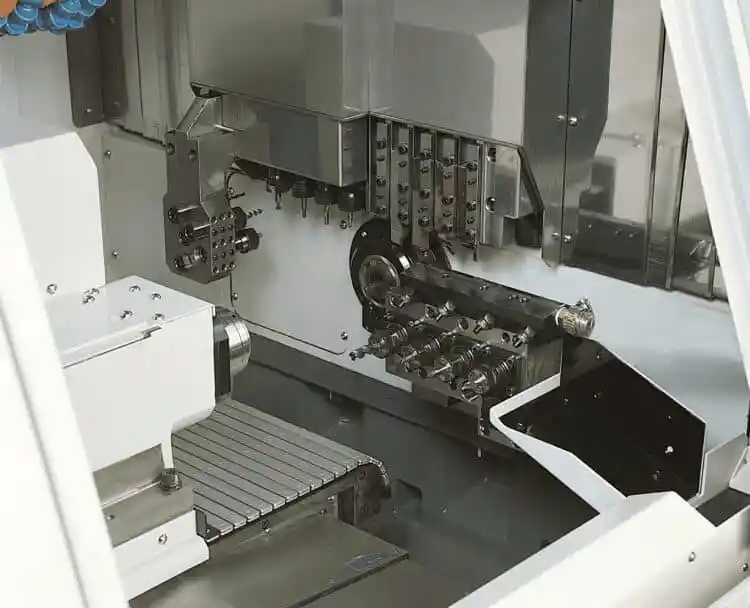
A guide bushing is a precision support component used in Swiss-type sliding-headstock lathes.
Unlike conventional turning arrangements where the workpiece may extend a significant distance from the chuck, a Swiss-type lathe supports the bar stock close to the cutting area.
As the sliding headstock moves along the Z-axis, the bar passes through the guide bushing. The bushing provides radial support near the cutting tool while allowing the required axial feeding movement.
Its main functions include:
- Workpiece Support: Reduces unsupported bar length and helps limit bending under cutting forces.
- Vibration Control: Provides support near the cutting zone, helping improve machining stability.
- Dimensional Consistency: Supports more predictable machining of slender components when the bar and guide bushing are correctly matched.
- Surface Quality: Helps reduce machining defects associated with excessive workpiece deflection and vibration.
Guide bushings are particularly useful when manufacturing long, small-diameter components such as medical instrument parts, precision shafts, electronic components, and industrial fasteners.
A guide bushing does not independently guarantee a specific machining tolerance. Final accuracy also depends on the machine, cutting tools, workpiece material, bar quality, and machining parameters.
2. Structural Design and Key Parameters
Guide bushings must provide sufficient radial support while allowing the workpiece to rotate and move axially as required by the machine design.
Important considerations include:
Guide Bushing Bore Diameter
The internal guide surface must match the bar stock dimensions.
Excessive clearance can reduce support effectiveness, while insufficient clearance can increase friction, generate heat, and interfere with bar feeding.
Bar Stock Quality
Bar diameter tolerance, roundness, straightness, and surface condition affect guide bushing performance.
Certain guide-bushing applications require precision-ground bar stock to maintain consistent running clearance.
Guide Surface Material
Wear-resistant materials, including carbide-lined designs, may be used to improve durability.
Specific guide surface materials and coatings should be selected according to the workpiece material and machine manufacturer's requirements.
Guide Bushing Alignment
The guide bushing must be properly aligned with the spindle and bar-feeding system.
Incorrect alignment can lead to friction, surface damage, unstable feeding, and dimensional variation.
II. Rotary vs. Fixed Guide Bushings: Key Differences
Swiss lathes commonly use rotary or fixed guide bushings.
Both support the bar stock near the cutting tool, but their operating principles and application considerations differ.
1. Rotary Guide Bushings
A rotary guide bushing, also called a rotating guide bushing, rotates with the bar stock.
Depending on the machine design, it may use a mechanically synchronized drive or another manufacturer-specific drive arrangement.
Technical Features
- Rotating Support: The guide bushing rotates in synchronization with the spindle and bar stock.
- Reduced Relative Friction: Synchronized rotation reduces relative rotational sliding between the bar and guide surface.
- High-Speed Capability: Suitable rotary guide bushing systems can support demanding spindle-speed requirements within their rated operating range.
- Workpiece Protection: Reduced rotational friction may help limit guide marks and heat generation on suitable materials.
Advantages
Rotary guide bushings can be useful when machining components where high spindle speed, material surface condition, or friction control are important considerations.
They may be suitable for precision shafts, medical components, and other slender parts, depending on machine capabilities and production requirements.
Limitations
Rotary systems may require additional bearings, drive components, synchronization, and maintenance.
Their performance depends on the condition and accuracy of the complete guide bushing assembly.
Rotary guide bushings are not automatically more accurate than fixed guide bushings. Actual results depend on the machine configuration, bar quality, and machining conditions.
2. Fixed Guide Bushings
A fixed guide bushing remains stationary while the bar stock rotates and moves axially through its internal guide surface.
The bushing provides radial support near the cutting tool without rotating with the workpiece.
Technical Features
- Stationary Support: The guide bushing remains fixed relative to the machine structure.
- Direct Radial Guidance: The bar rotates within the guide surface.
- Simpler Construction: Fixed designs generally avoid the rotating drive components used by synchronized rotary systems.
- Friction Management: Proper running clearance, lubrication, and bar surface quality are important because the rotating bar moves against the stationary guide surface.
Advantages
Fixed guide bushings can provide stable support and may be suitable for demanding precision applications when correctly adjusted.
Their relatively simple operating principle can also reduce the complexity of the guide bushing assembly.
Limitations
The relative rotation between the bar and guide surface creates friction.
If clearance, lubrication, or bar surface quality is unsuitable, the process may produce excessive heat, guide marks, or unstable material feeding.
3. Rotary vs. Fixed Guide Bushing Comparison
| Comparison Factor | Rotary Guide Bushing | Fixed Guide Bushing |
|---|---|---|
| Operating Principle | Rotates with the bar stock | Remains stationary |
| Relative Rotational Friction | Generally lower when properly synchronized | Requires greater attention to friction |
| Main Advantage | Reduced rubbing between bar and guide surface | Stable radial support with simpler guide arrangement |
| Spindle Speed | Depends on drive and bearing ratings | Depends on friction, lubrication, and machine design |
| Bar Stock Requirements | Suitable diameter and surface quality remain important | Running clearance and bar surface condition are especially important |
| Maintenance | Drive, bearings, alignment, and lubrication where applicable | Guide wear, clearance, alignment, and lubrication |
| Precision Capability | Depends on the complete machining system | Depends on the complete machining system |
Both types can be used to machine slender components. Workpiece length alone does not determine whether a rotary or fixed guide bushing should be selected.
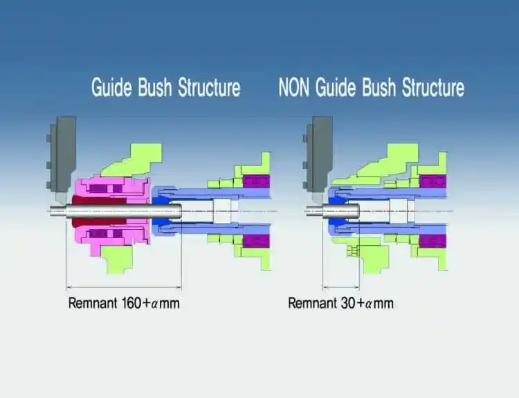
4. What About Guide-Bushing-Less Machining?
Some Swiss-type lathes can operate without a guide bushing.
In this arrangement, the workpiece is supported primarily by the spindle collet, with the cutting position kept close to the clamping point.
Guide-bushing-less machining may be suitable for short components that have sufficient rigidity.
Its potential advantages include:
- Reduced bar remnant waste
- Less dependence on precision-ground bar stock in suitable applications
- Simplified setup for certain short-part operations
- Improved material utilization
However, removing the guide bushing reduces the near-tool support available for longer or more flexible workpieces.
Guide-bushing-less operation should only be considered when the machine supports this configuration and the part geometry is suitable.
III. How Guide Bushings Improve Swiss Lathe Machining
1. Machining Accuracy and Stability
The primary advantage of a guide bushing is its ability to support the bar stock close to the cutting point.
This support reduces the effective unsupported length of the workpiece and helps control deflection under cutting forces.
As a result, correctly configured guide bushings can improve:
- Dimensional consistency
- Surface finish stability
- Workpiece support during turning
- Machining reliability for slender parts
However, the achievable tolerance and surface roughness depend on the complete machine setup.
Guide bushing condition is one factor among many, including spindle accuracy, cutting tool geometry, workholding, and material characteristics.
2. Production Efficiency
Stable support near the cutting zone can allow manufacturers to use appropriate machining strategies for slender components.
In suitable applications, this may reduce the need for repeated light cuts or unnecessary workpiece repositioning.
For automated bar-fed production, consistent guide bushing adjustment also helps maintain reliable material feeding.
The actual productivity benefit depends on the component geometry, cutting conditions, machine capabilities, and production process.
3. Cost and Material Utilization
Guide bushing selection also affects production costs.
Important factors include:
- Guide bushing purchase and replacement costs
- Bar stock preparation requirements
- Material waste and remnant length
- Maintenance and adjustment time
- Machining stability and rejected parts
For long, slender components, guide bushing support may justify the additional material preparation and setup requirements.
For shorter parts, guide-bushing-less operation may reduce material waste if the machine and application allow it.
The most economical arrangement is the one that meets the required part quality at an acceptable total production cost.
IV. Guide Bushing Materials, Lubrication, and Wear Resistance
1. Guide Surface Materials
Guide bushings may use hardened steel, carbide-lined surfaces, or other wear-resistant materials depending on the design.
Hardened Steel
Hardened steel can provide suitable strength and wear resistance for certain guide bushing applications.
Its performance depends on material grade, heat treatment, surface finish, and operating conditions.
Tungsten Carbide
Carbide-lined guide bushings can offer high wear resistance and may be useful in demanding production environments.
Their suitability depends on the intended bar material, loading conditions, and guide surface design.
Specialized Surface Treatments
Certain guide bushings may use surface treatments or coatings to improve wear resistance or reduce friction.
Coating selection must account for the base material, bar surface, lubrication conditions, and manufacturer specifications.
There is no universal coating that performs best for every workpiece material.
2. Lubrication and Thermal Management
Proper lubrication helps reduce friction and wear between contacting surfaces.
The lubrication requirements depend on whether the bushing is fixed or rotary, the bearing arrangement, and the machine's lubrication system.
For fixed guide bushings, friction between the rotating bar and stationary guide surface requires particular attention.
Rotary guide bushing assemblies may also require lubrication of their bearings or drive components.
Operators should use the lubricant type, supply method, and maintenance intervals specified by the machine manufacturer.
Excessive friction, incorrect clearance, insufficient lubrication, or damaged guide surfaces can cause abnormal temperature increases and machining problems.
3. Bar Stock and Guide Bushing Compatibility
Bar stock quality is an important but sometimes overlooked part of guide bushing performance.
Before selecting or adjusting a guide bushing, check:
- Bar diameter and tolerance
- Roundness and straightness
- Surface finish
- Material characteristics
- Compatibility with the selected guide bushing
- Requirements of the bar feeder and spindle system
A guide bushing cannot compensate for all material variations.
Poor-quality bar stock may still cause dimensional inconsistency, friction, vibration, or surface damage even when the machine is correctly adjusted.
V. Guide Bushing Installation, Adjustment, and Maintenance
1. Key Installation and Adjustment Steps
Correct installation and adjustment are essential for guide bushing performance.
Alignment Verification
Confirm that the guide bushing is correctly aligned with the spindle and material-feeding system.
Use the measurement and adjustment methods specified for the machine.
Running Clearance Adjustment
Set the guide bushing according to the actual bar diameter and the manufacturer's approved procedure.
The bar must be adequately supported while retaining the ability to rotate and feed as intended.
Too much clearance can reduce support effectiveness. Too little clearance can increase friction and cause feeding problems.
Lubrication System Inspection
Check that the relevant lubrication system is operating correctly.
The required lubricant, pressure, flow, and service procedures vary between machines and guide bushing designs.
Setup Verification
After adjustment, use the manufacturer's prescribed checking procedure to confirm stable bar movement and guide bushing operation before production.
2. Daily Maintenance
Routine maintenance helps prevent premature guide bushing wear and machining instability.
Wear Inspection
Inspect the guide surface for scratches, scoring, abnormal wear, and other visible damage.
If dimensional problems appear, evaluate the bushing condition using appropriate measuring equipment.
Cleaning
Remove accumulated chips and contamination according to the machine's safety procedures.
Avoid directing compressed air into sensitive spindle, bearing, or guide bushing assemblies unless specifically permitted by the manufacturer.
Lubrication Checks
Inspect the lubrication system and perform maintenance at the intervals specified in the machine documentation.
Bar Stock Inspection
Monitor incoming material for diameter variation, poor straightness, and surface defects that could affect guide bushing operation.
3. Common Guide Bushing Problems and Solutions
| Problem | Possible Causes | Recommended Checks |
|---|---|---|
| Machining Accuracy Out of Tolerance | Guide bushing wear, excessive clearance, alignment errors, or bar variation | Check bushing condition, bar quality, alignment, and machine setup |
| Abnormal Vibration | Insufficient support, unstable cutting, worn components, or unsuitable bar stock | Inspect clearance, tool condition, and cutting parameters |
| Scratches on Workpiece Surface | Excessive friction, guide surface damage, contamination, or poor lubrication | Inspect the guide surface, clean the assembly, and verify lubrication |
| Excessive Guide Bushing Temperature | Tight clearance, lubrication problems, or mechanical damage | Stop and inspect the system according to the machine's safety procedure |
| Unstable Bar Feeding | Incorrect adjustment, material variation, or bar-feeder misalignment | Check the guide bushing setting, bar dimensions, and feeding system |
When troubleshooting, avoid adjusting multiple variables simultaneously.
Identify the likely cause, verify the condition, and follow the manufacturer's maintenance and adjustment instructions before restarting production.
VI. How to Choose the Right Guide Bushing for a Swiss Lathe
1. Evaluate Workpiece Requirements
Guide bushing selection should begin with the workpiece rather than a fixed spindle-speed or material-hardness threshold.
| Workpiece or Production Requirement | Selection Consideration |
|---|---|
| Long, slender components | Guide bushing support is generally beneficial |
| High spindle speed or friction-sensitive bar surfaces | Evaluate a suitable rotary guide bushing |
| Precision turning with stable bar dimensions | Evaluate fixed and rotary configurations according to process requirements |
| Short, relatively rigid components | Consider guide-bushing-less machining if supported |
| Variable bar diameter or surface condition | Check material preparation and guide bushing adjustability |
| Expensive bar stock and significant remnant waste | Compare material utilization between supported operating modes |
The correct choice depends on how the workpiece behaves during machining, not simply whether the material is hard or soft.
2. Machine Tool Compatibility Assessment
Before selecting a guide bushing, verify compatibility with the Swiss-type lathe.
Important factors include:
Guide Bushing System
Confirm which fixed, rotary, or guide-bushing-less configurations the machine supports.
Not every machine can switch freely between these modes.
Spindle and Drive Arrangement
Rotary guide bushings require an appropriate drive and synchronization arrangement.
Compatibility must be confirmed from the machine's technical specifications.
Bar Capacity and Machining Length
Check the permitted bar diameter, guide bushing dimensions, machining stroke, and maximum machining length for the selected configuration.
Lubrication and Maintenance
Confirm the lubrication requirements and available maintenance support for the guide bushing assembly.
Production Requirements
Consider machining accuracy, workpiece material, batch size, surface requirements, and the frequency of setup changes.
3. Economic Considerations
The purchase price of a guide bushing is only one part of the overall cost.
The most suitable configuration should be evaluated against:
- Equipment and accessory investment
- Bar stock preparation costs
- Material remnant and scrap
- Maintenance requirements
- Setup and changeover time
- Tool wear and machining consistency
- Production volume
For example, a workshop producing long precision shafts may benefit from the support provided by a guide bushing.
A manufacturer producing short components from expensive bar stock may obtain better material utilization from a compatible guide-bushing-less setup.
However, cost savings and payback periods must be calculated using actual machine specifications, material prices, production data, and maintenance costs.
There is no universal return-on-investment figure that applies to every guide bushing configuration.
VII. Conclusion
Guide bushings are important components in Swiss-type lathes because they support bar stock close to the cutting tool and help control workpiece deflection during precision machining.
Rotary and fixed guide bushings offer different operating characteristics. Rotary designs reduce relative rotational friction, while fixed designs provide stationary guidance that requires careful clearance and lubrication management.
For certain short components, guide-bushing-less machining may provide an alternative when supported by the machine.
Choosing the right guide bushing requires evaluating workpiece geometry, bar quality, machining speed, accuracy requirements, and machine compatibility.
Proper installation, adjustment, and maintenance are equally important for reliable operation.
MINNUO provides CNC machine tool solutions for different precision manufacturing applications. Manufacturers evaluating Swiss-type lathes should compare available guide bushing configurations and confirm their suitability against the intended workpiece and production requirements.
The right guide bushing arrangement helps create a stable machining process while balancing precision, efficiency, and operating costs.

 Email
 sales1: +86 15312799623